7 ) zero point return operation and parameters – Yaskawa MP2000 Series: Built-in SVB or SVB-01 Motion Module User Manual
Page 182
6.2 Motion Command Details
6.2.3 Zero Point Return (ZRET)
6-21
Motion Commands
( 7 ) Zero Point Return Operation and Parameters
With an incremental encoder, there are 13 different methods that can be performed for the zero point return operation.
This section explains the operation that occurs after starting a zero point return and the parameters that need to be set
before executing the command.
None of the methods shown here are available with the SVR because it only supports absolute encoders.
[ a ] DEC1 + C Method (OW
3C = 0)
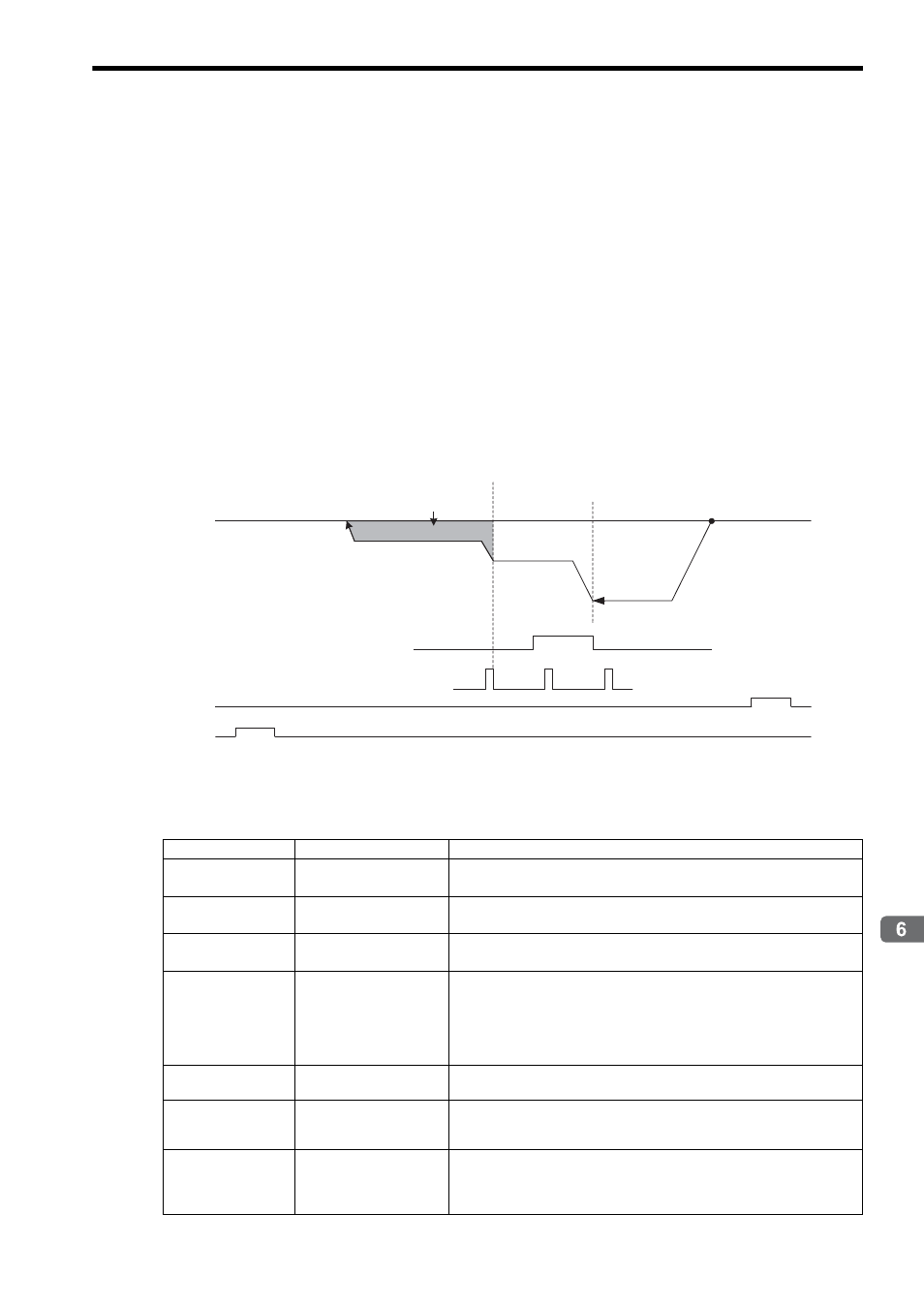
Operation after Zero Point Return Starts
Travel is started at the zero point return speed in the direction specified in the parameters.
When the rising edge of the DEC1 signal is detected, the speed is reduced to the approach speed.
When the first phase-C pulse is detected after passing the DEC1 signal at the approach speed, the speed is reduced to
the creep speed and positioning is performed.
When the positioning has been completed, a machine coordinate system is established with the final position as the
zero point.
The moving amount after the phase-C pulse is detected is set in the Zero Point Return Travel Distance (OL
42).
If an OT signal is detected during the zero point return operation, an OT alarm will occur.
* 1. The SERVOPACK DEC signal.
* 2. The SERVOPACK P-OT signal.
* 3. The SERVOPACK N-OT signal.
Setting Parameters
Parameter
Name
Setting
OW
3C
Zero Point Return
Method
0: DEC1 + Phase-C
OW
09, Bit 3
Zero Point Return
Direction Selection
Set the zero point return direction.
OL
10
Speed Reference
Setting
Set the speed to use when starting a zero point return.
Only a positive value can be set; a negative value will result in an error.
OW
18
Override
This parameter allows the Zero Point Return speed to be changed without
changing the Speed Reference Setting (OL
10). Set the speed as a per-
centage of the Speed Reference Setting. This setting can be changed during
operation.
Setting range: 0 to 32767 (0% to 327.67%) Setting unit: 1 = 0.01%
Example: Setting for 50%: 5000
OL
3E
Approach Speed
Set the speed to use after detecting the DEC1 signal.
Only a positive value can be set; a negative value will result in an error.
OL
40
Creep Rate
Set the speed to use after detecting the first phase-C pulse after passing the
DEC1 signal. Only a positive value can be set; a negative value will result in
an error.
OL
42
Zero Point Return Travel
Distance
Set the travel distance from the point where the first phase-C pulse is
detected after passing the DEC1 signal.
If the sign is positive, travel will be toward the zero point return direction; if
the sign is negative, travel will be away from the zero point return direction.
DEC1 signal
∗1
N-OT
∗3
P-OT
∗2
Start
Zero Point
Phase-C pulse
Zero Point Return Travel Distance
(OL
42)
Creep Rate
(OL
40)
Approach Speed
(OL
3E)
Zero Point Return Speed
(OL
10)