2 control block diagram for phase control – Yaskawa MP2000 Series: Built-in SVB or SVB-01 Motion Module User Manual
Page 324
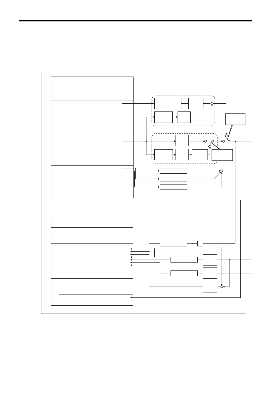
8.2 Phase Control
8.2.2 Control Block Diagram for Phase Control
8-12
8.2.2 Control Block Diagram for Phase Control
MP2000-series Machine Controller
SVB
Move command generation processing
(When using an electronic shaft)
Target position
difference
operation
+
+
Target
position
operation
(Integration)
Target
position
operation
(Integration)
+
Move command generation processing
(When using an electronic cam)
Difference
operation
Phase Reference
Creation
Calculation Disable
(OW
05.Bit1)
ON
ON
OFF
OFF
Difference
operation
[UNIT]
ω
[pulse]
[UNIT]
ω
[pulse]
[UNIT]
ω
[pulse]
Speed reference
unit change
OL
10 Speed Reference Setting
OL
28 Phase Correction Setting
OW
31 Speed Compensation
OL
16 Secondly Speed Compensation
OW
3A Filter Time Constant
OL
48 Zero Point Position in Machine Coordinate System Offset
OL
4A Work Coordinate System Offset
OL
1E Width of Positioning Completion
OL
20 NEAR Signal Output Width
OL
22 Error Count Alarm Detection
OW
26 Positioning Completion Check Time
OW
00 RUN Command Setting
OW
03 Function Setting 1
OW
05 Function Setting 3
OW
08 Motion Command
OW
09 Motion Command Control Flag
OW
0A Motion Subcommand
OL
4C Number of POSMAX Turns Presetting Data
IW
00 RUN Status
IL
02 Warning
IL
04 Alarm
IW
08 Motion Command Response Code
IW
09 Motion Command Status
IW
0A Motion Subcommand Response Code
Position Management Status
Target Position in Machine Coordinate System (TPOS)
IW
0B Subcommand Status
IW
0C
IL
0E
IL
10
IL
12
IL
14
IL
16
IL
18
IL
1A
IL
1C
IL
1E
IL
20
IW
2C Servo Driver Status
IW
2D
IW
2E
IW
2F
IW
30
IL
40 Feedback Speed
IL
42 Feedback Torque/Thrust
Target Position Difference Monitor
Number of POSMAX Turns
Speed Reference Output Monitor
Calculated Position in Machine Coordinate System (CPOS)
Machine Coordinate System Reference Position (MPOS)
CPOS for 32bit (DPOS)
Machine Coordinate System Feedback Position (APOS)
Machine Coordinate System Latch Position (LPOS)
Position Error (PERR)
Servo Driver Alarm Code
Servo Driver I/O Monitor
Servo Driver User Monitor Information
Servo Driver User Monitor 2
Ǜ
POSMAX processing
Unit change
[pulse]
ω
[UNIT]
[pulse]
ω
[UNIT]
[pulse]
ω
[UNIT]
POSMAX processing
POSMAX processing
+
+
+
+
Run Settings
Speed/Position Reference
Gain
Time Constants
Coordi- nate
Run Information
Motion Command Information
SERVOPACK Information
Phase
compensation
type
(OW
09.Bit6)
Position informati
on
Unit change
Unit change
Unit change
Unit change
Unit change
Speed reference
unit change
Speed reference
unit change