4 interpolation (interpolate), 1 ) executing/operating procedure – Yaskawa MP2000 Series: Built-in SVB or SVB-01 Motion Module User Manual
Page 197
6.2 Motion Command Details
6.2.4 Interpolation (INTERPOLATE)
6-36
6.2.4 Interpolation (INTERPOLATE)
The INTERPOLATE command positions the axis according to the target position that changes in sync with the high-
speed scan. The positioning data is generated by a ladder program.
Speed feed forward compensation can be applied.
Torque feed forward gain can be used when interpolation commands (INTERPOLATE) are sent using SGDS SER-
VOPACKs.
Torque feed forward gain is set in Torque/Thrust Reference Setting (setting parameter OL
0C). The required con-
ditions are as follows:
• SERVOPACK parameter Pn002.0 = 2
• SGDS communication interface version 8 or later
When using an SGDV SERVOPACK, the torque limit can be set and changed during SERVOPACK operation. For
details, refer to Setting and Changing Torque Limit during SGDV SERVOPACK Operations of 4.4.2 ( 12 ).
( 1 ) Executing/Operating Procedure
1.
Check to see if all the following conditions are satisfied.
2.
Set the following motion setting parameters.
Position Reference Setting: OL
1C
Filter Type Selection: OW
03, bits 8 to B
Speed Loop P/PI Switch: OW
01
Speed Feed Forward Amends: OW
30
3.
Set the parameter OW
08 to 4 to execute an INTERPOLATE command.
4 is stored in IW
08 during positioning.
4.
Refresh the value of OL
1C (Position Reference Setting) at every high-speed scan.
The target position is updated to the refreshed value of OL
1C at every high-speed scan.
*
The difference between the target position of one high-speed scan and that of the next high-speed scan will be the
moving speed.
When the axis reaches the target position, bit 1 of IW
0C will turn ON and positioning will be completed.
* When the incremental addition mode is set for bit 5 of OW
09 “Position Reference Type,” the following
value will be set to the current target position: Previous target position + Difference between the current value
and the previous value of the Position Reference Setting
5.
Set OW
08 to 0 to execute the NOP motion command and then complete the positioning operation.
R
No.
Execution Conditions
Confirmation Method
1
There are no alarms.
Both IL
02 and IL
04 are 0.
2
The Servo ON condition.
IW
00, bit 1 is ON.
3
Motion command execution has been completed.
IW
08 is 0 and IW
09, bit 0 is OFF.
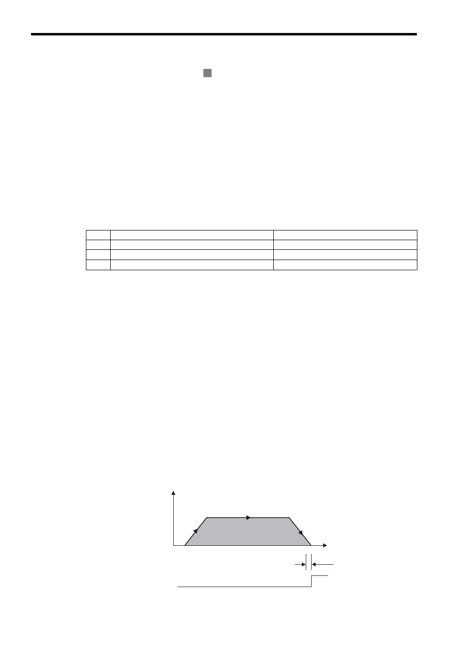
Position
0
Width of Positioning Completion
POSCOMP
Speed (%)
Time (t)
INTERPOLATE Operating Pattern