G.4 restrictions on the use of motion parameters, A-25, 1 ) invalid parameters when using an m-ii stepper – Yaskawa MP2000 Series: Built-in SVB or SVB-01 Motion Module User Manual
Page 514
Appendix G Settings when Connecting MECHATROLINK-II Compatible Stepping Motor Drivers
G.4 Restrictions on the Use of Motion Parameters
A-25
Appendices
G.4
Restrictions on the Use of Motion Parameters
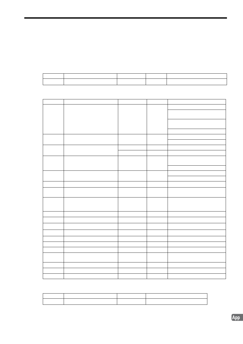
When using an M-II Stepper, the specifications of some motion parameters are different from when using servos.
( 1 ) Invalid Parameters When Using an M-II Stepper
Fixed Parameters
Setting Parameters
Monitoring Parameter
No.
Name
Setting Range
Default
Description
16
Backlash Compensation Amount -2
31
to 2
31
-1
0
1 = 1 reference unit
Register
Name
Setting Range
Default
Description
OW
00
Run Command Setting
Bit setting
0
Bit 4: Latch Detection Demand
Bit 8: Forward Outside Limiting
Torque/Thrust Input
Bit 9: Reverse Outside Limiting
Torque/Thrust Input
Bit 11: Integration Reset
OW
01
Mode Setting 1
Bit setting
0
Bit 3: Speed Loop P/PI Switch
Bit 4: Gain Switch
OW
03
Function Setting 1
0 to 2
0
Bits 8 to 11: Filter Type Selection
0 or 1
0
Bits 12 to 15: Torque Unit Selection
OW
05
Function Setting 3
Bit setting
0
Bit 1: Phase Reference Creation
Calculation Disable
Bit 11: Zero Point Return Input Signal
OW
09
Motion Command Control Flag
Bit setting
0
Bit 4: Latch Zone Effective Selection
Bit 6: Phase Compensation Type
OL
0C
Torque/Thrust Reference Setting
-2
31
to 2
31
-1
0
1 = 0.01% or 0.0001%
OW
0E
Speed Limit Setting at the
Torque/Thrust Reference
-32768 to 32767
15000
1 = 0.01%
OL
14
Positive Side Limiting Torque/
Thrust Setting at the Speed Ref-
erence
-2
31
to 2
31
-1
30000
1 = 0.01%
OL
1E
Width of Positioning Completion
0 to 65535
100
1 = 1 reference unit
OL
28
Phase Correction Setting
-2
31
to 2
31
-1
0
1 = 1 reference unit
OL
2A
Latch Zone Lower Limit Setting
-2
31
to 2
31
-1
-2
31
1 = 1 reference unit
OL
2C
Latch Zone Upper Limit Setting
-2
31
to 2
31
-1
2
31
-1
1 = 1 reference unit
OW
2E
Position Loop Gain
0 to 32767
300
1 = 0.1/s
OW
2F
Speed Loop Gain
1 to 2000
40
1 = 1 Hz
OW
30
Speed Feed Forward Amends
0 to 32767
0
1 = 0.01%
OW
32
Position Integration Time Con-
stant
0 to 32767
0
1 = 1 ms
OW
34
Speed Integration Time Constant
15 to 65536
2000
1 = 0.01 ms
OW
3A
Filter Time Constant
0 to 65535
0
1 = 0.1 ms
OW
3C
Zero Point Return Method
0 to 19
0
−
Register
Name
Range
Description
IL
42
Feedback Torque/Thrust
-2
31
to 2
31
-1
1 = 0.01% or 0.0001%