7 ) user constant ram writing, 8 ) user constant eeprom writing – Yaskawa MP2000 Series: Built-in SVB or SVB-01 Motion Module User Manual
Page 383
10.3 Main Commands and Subcommands
10.3.3 Command Details
10-19
Settings for Connecting Inverters
Monitoring Parameters
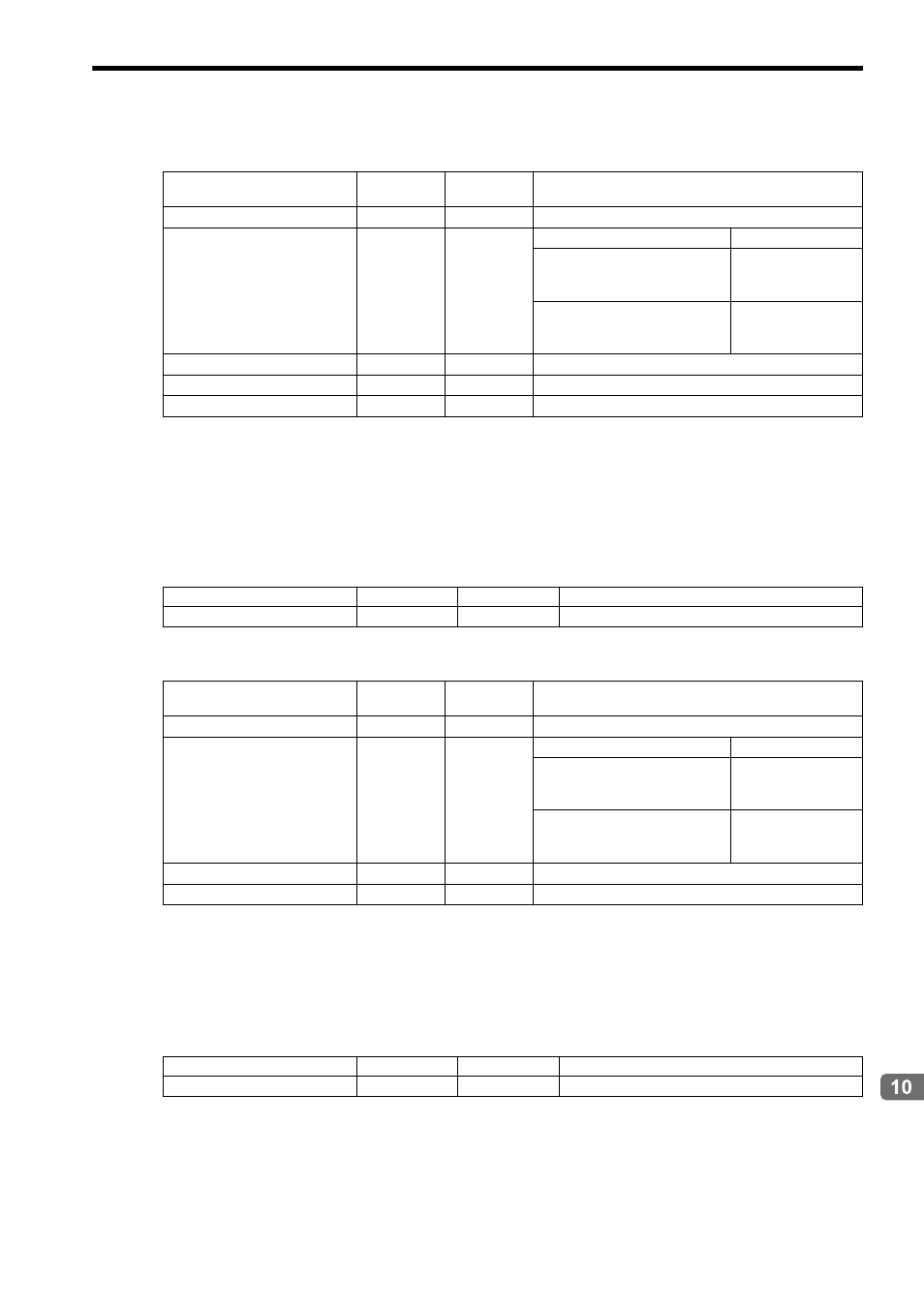
( 7 ) User Constant RAM Writing
Description
Saves the parameter data written by executing Write User Constant in the Inverter volatile memory to validate the data.
With VSminiV7, the data written by executing Write User Constant will be validated without executing this command.
Setting Parameters
Monitoring Parameters
( 8 ) User Constant EEPROM Writing
Description
Saves the parameter data written by executing Write User Constant in the Inverter nonvolatile memory.
Setting Parameters
Name
Register No.
Setting
Range
Remarks
Command Response Code
IW
08
0 to 8
05: Alarm History Monitor
Command Status
IW
09
Bit
Bit 0 (Command execution flag)
ON during execution
Bit 3 (Command error completed
status)
ON when an error
occurs during com-
mand processing
Bit 8 (Command execution com-
pleted)
ON when command
execution is com-
pleted.
Status
IW
10
Bit
Inverter status
Response Alarm Code
IW
30
0 to FFFFH
Inverter alarm code
Inverter Alarm Code
IW
32
0 to FFFFH
The alarm history is read out
Name
Register No.
Setting Range
Remarks
Command Code
OW
08
0 to 8
06: User Constant RAM Writing
Name
Register No.
Setting
Range
Remarks
Command Response Code
IW
08
0 to 8
06: User Constant RAM Writing
Command Status
IW
09
Bit
Bit 0 (Command execution flag)
ON during execution
Bit 3 (Command error completed
status)
ON when an error
occurs during com-
mand processing
Bit 8 (Command execution com-
pleted)
ON when command
execution is com-
pleted.
Status
IW
10
Bit
Inverter status
Response Alarm Code
IW
30
0 to FFFFH
Inverter alarm code
Name
Register No.
Setting Range
Remarks
Command Code
OW
08
0 to 8
07: User Constant EEPROM Writing