M ] input only method (ow 3c = 19) – Yaskawa MP2000 Series: Built-in SVB or SVB-01 Motion Module User Manual
Page 196
6.2 Motion Command Details
6.2.3 Zero Point Return (ZRET)
6-35
Motion Commands
[ m ] INPUT Only Method (OW
3C = 19)
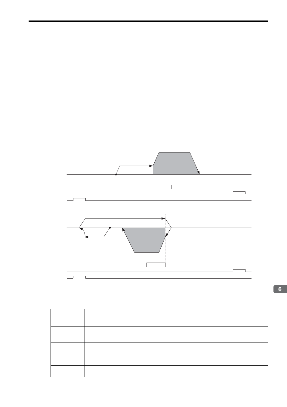
Operation after Zero Point Return Starts
Travel is started at the creep speed in the direction specified by the sign of the creep speed.
When the rising edge of the INPUT signal is detected, the positioning is performed at the positioning speed.
When the positioning has been completed, a machine coordinate system is established with the final position as the
zero point.
The moving amount after the rising edge of the Zero Point Return Input Signal is detected is set in the Zero Point
Return Travel Distance. The positioning speed is set in the Speed Reference Setting.
If an OT signal is detected during creep speed operation, an OT alarm will not occur, the direction will be reversed,
and a search will be made for the Zero Point Return Input Signal.
If an OT signal is detected during positioning speed operation, an OT alarm will occur.
The Zero Point Return Input Signal is allocated to the motion setting parameter OW
05 bit B, allowing the zero
point return operation to be performed without actually wiring a signal. This method can thus be used to temporarily
set the zero point during trial operation.
Detecting the rising edge of the Zero Point Return Input Signal is performed using software processing. The position
where positioning is completed will depend on the high-speed scan setting, positioning speed, etc. Do not use this
method if repeat accuracy is required in the position where the zero point return operation is completed.
* 1. The SERVOPACK P-OT signal.
* 2. The SERVOPACK N-OT signal.
The stopping method when the OT signal is detected depends on the setting of SERVOPACK parameters.
Setting Parameters
Parameter
Name
Setting
OW
3C
Zero Point Return
Method
19: INPUT Only Method
OL
10
Speed Reference
Setting
Set the positioning speed to use after detecting the Zero Point Return Input Signal.
The sign is ignored. The travel direction will depend on the sign of the Zero Point
Return Travel Distance.
OL
40
Creep Rate
Set the speed and the travel direction (sign) to use when starting a zero point return.
OL
42
Zero Point Return
Travel Distance
Set the distance to travel from the point the Zero Point Return Input Signal
is detected.
The travel direction will depend on the sign.
OW
05, Bit B
Zero Point Return
Input Signal
This signal must be turned ON from the ladder program.
Zero Point Return Input Signal
(OW
05, bit B)
Start
Zero Point
N-OT
*2
P-OT
*1
Positioning Speed
(OL
10)
Creep Rate
(OL
40)
Zero Point Return
Travel Distance
(OL
42)
Zero Point Return Input Signal
(OW
05, bit B)
Start Zero Point
N-OT
*2
P-OT
*1
Creep Rate
(OL
40)
Creep Rate
(OL
40)
Zero Point Return
Travel Distance
(OL
42)
Positioning Speed
(OL
10)