4 svr operation, 1 ) svr execution timing, 2 ) processing time – Yaskawa MP2000 Series: Built-in SVB or SVB-01 Motion Module User Manual
Page 31
1.3 SVR Virtual Motion Module
1.3.4 SVR Operation
1-15
Overview
1.3.4 SVR Operation
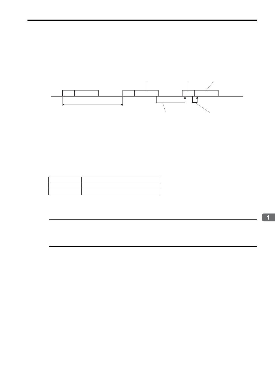
( 1 ) SVR Execution Timing
The SVR is processed at the beginning of the high-speed scan. SVR processing is performed in the next scan after
specifying and the processing results are reflected in the monitoring parameters.
( 2 ) Processing Time
When fixed parameter No.0 (Selection of Operation Modes) is set to 0 (Normal Operation Mode), services are started
for each of the 16 SVR module virtual axes.
The default for the Selection of Operation Modes parameter is 1 (Axis Unused).
The following table gives guidelines for the processing time required for each SVR axis.
Number of axes: The number of axes (1 to 16) when Selection of Operation Modes (fixed parameter No.0) is set to
Normal Operation Mode (0).
The formula listed above do not apply when the number of axes is 0.
Differences from SVB Simulation Mode
Simulation mode does not have a positioning function, so the position data is refreshed in one scan to the final target position.
The SVR has its own positioning function that performs distribution, so like a real module, position data is refreshed each scan
for the final target position.
SVR
SVR
SVR
High-speed scan
H Drawing
Results of commands in the H
drawing are used in SVR
processing in the next scan.
H Drawing
H Drawing
SVR processing results
can be monitored in the H
drawing of the same scan.
Reflected in monitoring
parameters
Reference set
SVR processing
Command
MP2300
NOP
35 +14
× Number of axes (μs)
POSING
35 +36
× Number of axes (μs)