5 ) alarm monitor, 6 ) alarm history monitor – Yaskawa MP2000 Series: Built-in SVB or SVB-01 Motion Module User Manual
Page 389
10.3 Main Commands and Subcommands
10.3.4 Subcommand Details
10-25
Settings for Connecting Inverters
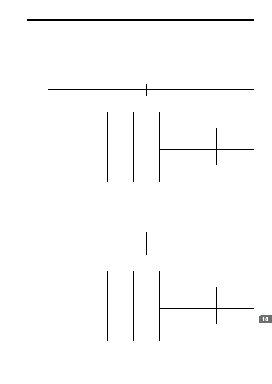
( 5 ) Alarm Monitor
Description
Reads out the alarm that is occurring in the Inverter.
Valid only in MECHATROLINK-II 32-byte mode.
Setting Parameters
Monitoring Parameters
( 6 ) Alarm History Monitor
Description
Reads out the Inverter alarm history.
Valid only in MECHATROLINK-II 32-byte mode
Setting Parameters
Monitoring Parameters
Name
Register No.
Setting Range
Remarks
Subcommand Code
OW
0A
0 to 9
04: Alarm Monitor
Name
Register No.
Setting
Range
Remarks
Subcommand Response Code
IW
0A
0 to 9
04: Alarm Monitor
Subcommand Status
IW
0B
Bit
Bit 0 (Command execution flag)
ON during execution
Bit 3 (Command error completed
status)
ON when an error
occurs during com-
mand processing.
Bit 8 (Command execution com-
pleted)
ON when command
execution is com-
pleted.
Subcommand Response Status
IW
31
Bit
Refer to Subcommand Response Status of 10.4.3 Monitor-
ing Parameter List.
Auxiliary Inverter Alarm Code
IW
33
0 to FFFFH
The currently occurring alarm that is read out.
Name
Register No.
Setting Range
Remarks
Subcommand Code
OW
0A
0 to 9
05: Alarm History Monitor
Auxiliary Inverter Alarm Monitor Num-
ber
OW
33
0 to 3
History monitor number
Name
Register No.
Setting
Range
Remarks
Subcommand Response Code
IW
0A
0 to 9
05: Alarm History Monitor
Subcommand Status
IW
0B
Bit
Bit 0 (Command execution flag)
ON during execution
Bit 3 (Command error completed
status
ON when an error
occurs during com-
mand processing.
Bit 8 (Command execution com-
pleted)
ON when command
execution is com-
pleted.
Subcommand Response Status
IW
31
Bit
Refer to Subcommand response Status of 10.4.3 Monitor-
ing Parameter List.
Auxiliary Inverter Alarm Code
IW
33
0 to FFFFH
The alarm history that is read out.