Yaskawa MP2000 Series: Built-in SVB or SVB-01 Motion Module User Manual
Page 109
4.4 MP2000 Series Machine Controller Parameter Details
4.4.2 Motion Setting Parameter Details
4-33
Motion Parameters
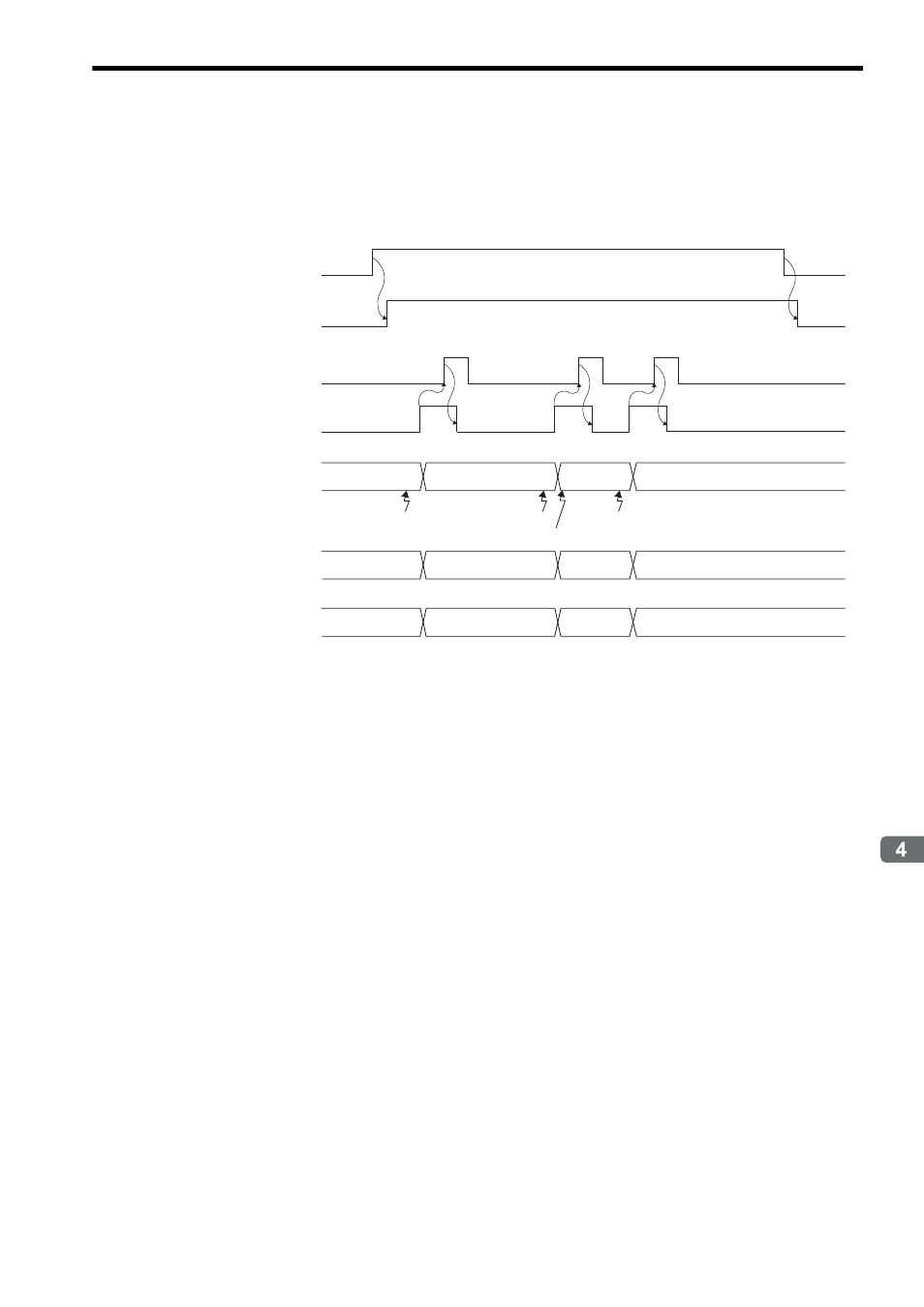
• Operation
For continuous latch operations, bit 4 of OW
00 is set to 1. After the latch has been confirmed as being com-
pleted, set bit 10 of OW
00 to 1 and bit 2 of IW
0C is forced OFF.
If the latch cycle is too short to match the scan cycle, the latch positions may not be recognized. To check if the
latch was successfully completed in the set sequence, use IW
44 or IW
45.
* This example shows when the output for the phase-C and EXT1 latches are constant and the latching action of
the EXT1 latch is bypassed.
The reported latching position ( ) is created by the phase-C latch and it can be checked at IW
44.
If the EXT latch is executed, the setting of IW
45 changes from 0 to 1.
Latch Completion
Status Clear Request
OW
00.bit 10
Machine Coordinate
System Latch Position
IL
18
Number of Continuous
Latch Sequence
Completion Cycles
IW
45
Latch Completion
Sequence Number
IW
44
Latch Complete
IW
0C.bit 2
Latch Mode
IW
00.bit 4
Latch Detection Demand
OW
00.bit 4
1
1
2
0
1
2
EXT1 Latch
C Latch
EXT1Latch
CLatch
- Tag Generator (30 pages)
- MP3300iec (82 pages)
- 1000 Hz High Frequency (18 pages)
- 1000 Series (7 pages)
- PS-A10LB (39 pages)
- iQpump Micro User Manual (300 pages)
- 1000 Series Drive Option - Digital Input (30 pages)
- 1000 Series Drive Option - CANopen (39 pages)
- 1000 Series Drive Option - Analog Monitor (27 pages)
- 1000 Series Drive Option - CANopen Technical Manual (37 pages)
- 1000 Series Drive Option - CC-Link (38 pages)
- 1000 Series Drive Option - CC-Link Technical Manual (36 pages)
- 1000 Series Drive Option - DeviceNet (37 pages)
- 1000 Series Drive Option - DeviceNet Technical Manual (81 pages)
- 1000 Series Drive Option - MECHATROLINK-II (32 pages)
- 1000 Series Drive Option - Digital Output (31 pages)
- 1000 Series Drive Option - MECHATROLINK-II Technical Manual (41 pages)
- 1000 Series Drive Option - Profibus-DP (35 pages)
- AC Drive 1000-Series Option PG-RT3 Motor (36 pages)
- Z1000U HVAC MATRIX Drive Quick Start (378 pages)
- 1000 Series Operator Mounting Kit NEMA Type 4X (20 pages)
- 1000 Series Drive Option - Profibus-DP Technical Manual (44 pages)
- CopyUnitManager (38 pages)
- 1000 Series Option - JVOP-182 Remote LED (58 pages)
- 1000 Series Option - PG-X3 Line Driver (31 pages)
- SI-EN3 Technical Manual (68 pages)
- JVOP-181 (22 pages)
- JVOP-181 USB Copy Unit (2 pages)
- SI-EN3 (54 pages)
- SI-ET3 (49 pages)
- MECHATROLINK-III (35 pages)
- EtherNet/IP (50 pages)
- SI-EM3 (51 pages)
- 1000-Series Option PG-E3 Motor Encoder Feedback (33 pages)
- 1000-Series Option SI-EP3 PROFINET (56 pages)
- PROFINET (62 pages)
- AC Drive 1000-Series Option PG-RT3 Motor (45 pages)
- SI-EP3 PROFINET Technical Manual (53 pages)
- A1000 Drive Option - BACnet MS/TP (48 pages)
- 120 Series I/O Modules (308 pages)
- A1000 12-Pulse (92 pages)
- A1000 Drive Software Technical Manual (16 pages)
- A1000 Quick Start (2 pages)
- JUNMA Series AC SERVOMOTOR (1 page)
- A1000 Option DI-101 120 Vac Digital Input Option (24 pages)