A-39, 1 ) connection management, 2 ) watchdog timer processing – Yaskawa MP2000 Series: Built-in SVB or SVB-01 Motion Module User Manual
Page 528: 3 ) interpolation segment distribution
Appendix I Servo Driver Transmission Reference Mode
I.1 What is Servo Driver Transmission Reference Mode?
A-39
Appendices
Appendix I Servo Driver Transmission Reference Mode
I.1
What is Servo Driver Transmission Reference Mode?
Users can directly send MECHATROLINK servo commands in Servo Driver Transmission Reference Mode.
Set the fixed parameter No. 0 (Selection of Operation Modes) of the corresponding axis to 3 (Servo Driver Transmis-
sion Reference Mode) to enable the mode.
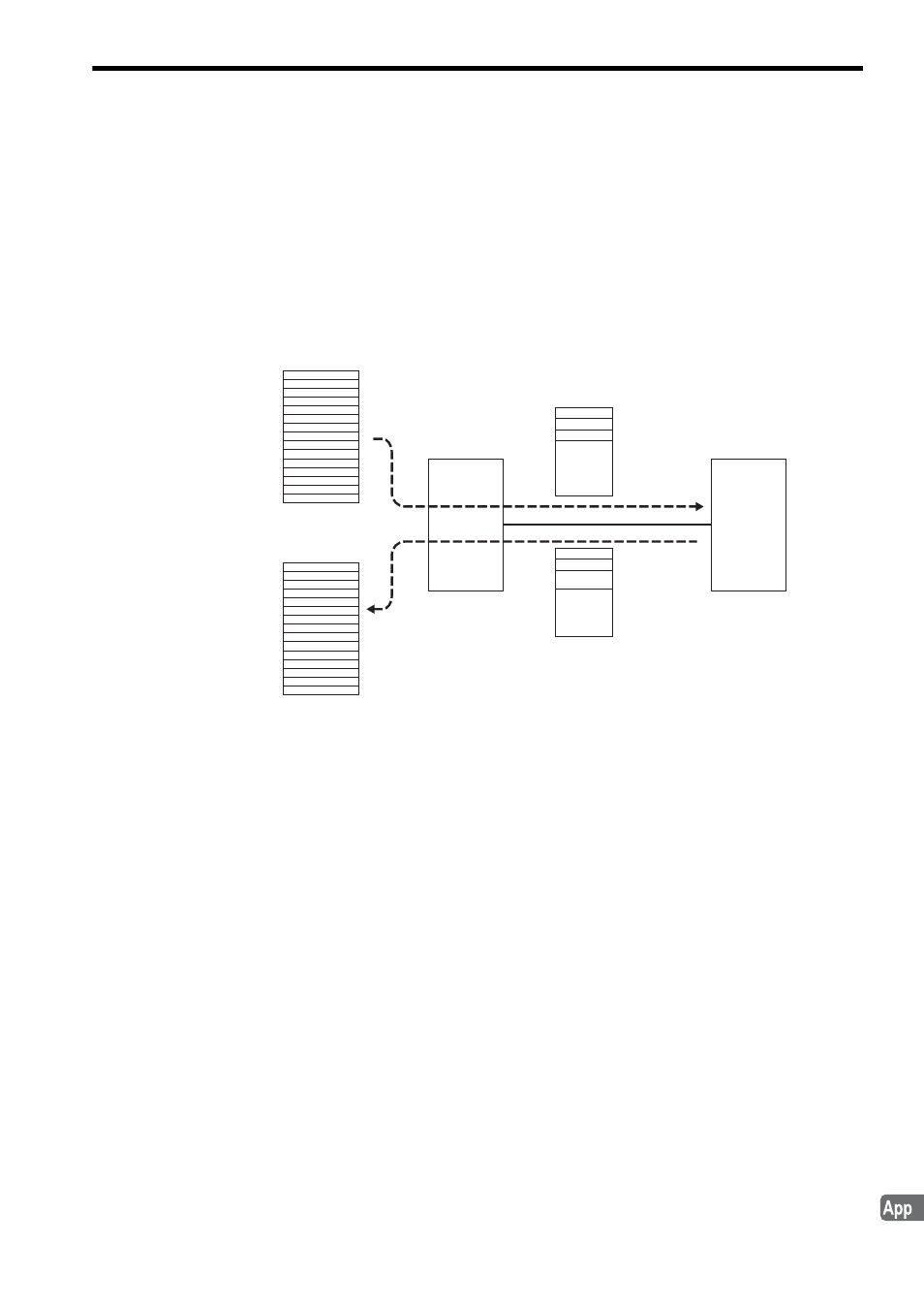
MECHATROLINK servo command data can be sent using the motion setting parameters OW
70 to OW
7E in
32-byte mode or OW
70 to OW
77 in 17-byte mode, and the response data can be received using the motion
monitoring parameters IW
70 to IW
7E in 32-byte mode or IW
70 to IW
77 in 17-byte mode.
Refer to the relevant SERVOPACK user’s manual for details on MECHATROLINK commands.
I.2
MECHATROLINK Communication Management by the System
( 1 ) Connection Management
When the power to the system is turned ON, the system will automatically execute the processing to shift the operation
to MECHATROLINK communication phase 3 (synchronous communication status) by establishing a connection and
synchronous communications.
When an alarm is cleared, the system automatically clears the alarms of MECHATROLINK connected servos. At the
same time, the system will execute processing to restore MECHATROLINK communication phase 3 (synchronous
communication status.)
( 2 ) Watchdog Timer Processing
The WDT field of the 16th byte (both command and response) of the MECHATROLINK servo command is used by
the system to automatically prepare transmission data and detect errors.
When an error is detected, the MECHATROLINK communication phase is shifted to phase 2 (asynchronous communi-
cation status) and then to phase 4 (communication stop status). As a result, the Motion Controller Operation Ready bit
(bit 0 of the motion monitoring parameter Drive Status) will be set to 0: Operation Not Ready.
( 3 ) Interpolation Segment Distribution
When the Interpolation Segment Distribution Processing bit (fixed parameter No. 1 Function Selection Flag 1, bit 8) is
set to 0 (enabled) and interpolation segment distribution per high-speed scan is constant, processing to control interpo-
lation segment distribution per MECHATROLINK communication cycle to be constant is implemented.
Setting parameters
OW
70
OW
7E
Monitoring parameters
IW
70
IW
7E
CMD
OPTION
RCMD
ALAM
STATUS
SVB
MECHATROLINK
servo commands
Command Data
MECHATROLINK
servo commands
Response Data
MECHATROLINK
servo
to
to