Yaskawa MP2000 Series: Built-in SVB or SVB-01 Motion Module User Manual
Built-in svb/svb-01 motion module, User’s manual, Machine controller mp2000 series
USER’S MANUAL
MANUAL NO. SIEP C880700 33F
Model: JAPMC-MC2100, JEPMC-MP2540-A
to C
JAPMC-MC2140, JEPMC-MP2500-D
JEPMC-MP2300, JEPMC-MP2540-D
JEPMC-MP2500-A
to C, JAPMC-MC2310
Built-in SVB/SVB-01
Motion Module
Machine Controller MP2000 Series
Overview
Settings and Installation
Self-configuration and Created Definition Files
Motion Parameters
Motion Parameter Setting Examples
Motion Commands
Switching Commands during Execution
Control Block Diagrams
Absolute Position Detection
Settings for Connecting Inverters
Utility Functions
Troubleshooting
Appendices
1
2
3
4
5
6
7
8
9
10
11
12
App
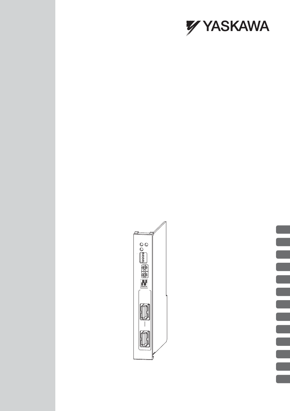
SVB-01
TX
ERR
RUN
SPD
SIZE
M/S
ON
OFF
×10
×1
M-I/II
CN1
CN2
Table of contents
Document Outline
- Front Cover
- Using this Manual
- Safety Information
- Safety Precautions
- Warranty
- Contents
- 1 Overview
- 2 Settings and Installation
- 3 Self-configuration and Created Definition Files
- 4 Motion Parameters
- 5 Motion Parameter Setting Examples
- 6 Motion Commands
- 6.1 Motion Commands
- 6.2 Motion Command Details
- 6.2.1 Position Mode (POSING) (Positioning)
- 6.2.2 Latch Target Positioning (EX_POSING) (External Positioning)
- 6.2.3 Zero Point Return (ZRET)
- 6.2.4 Interpolation (INTERPOLATE)
- 6.2.5 Interpolation Mode with Latch Input (LATCH)
- 6.2.6 Jog Mode (FEED)
- 6.2.7 Relative Position Mode (STEP) (Step Mode)
- 6.2.8 Set Zero Point (ZSET)
- 6.2.9 Change Acceleration Time (ACC)
- 6.2.10 Change Deceleration Time (DCC)
- 6.2.11 Change Filter Time Constant (SCC)
- 6.2.12 Change Filter Type (CHG_FILTER)
- 6.2.13 Change Speed Loop Gain (KVS)
- 6.2.14 Change Position Loop Gain (KPS)
- 6.2.15 Change Feed Forward (KFS)
- 6.2.16 Read User Constant (PRM_RD)
- 6.2.17 Write User Constant (PRM_WR)
- 6.2.18 Alarm Monitor (ALM_MON)
- 6.2.19 Alarm History Monitor (ALM_HIST)
- 6.2.20 Clear Alarm History (ALMHIST_CLR)
- 6.2.21 Absolute Encoder Reset (ABS_RST)
- 6.2.22 Speed Reference (VELO)
- 6.2.23 Torque /Thrust Reference (TRQ)
- 6.2.24 Phase References (PHASE)
- 6.2.25 Change Position Loop Integral Time Constant (KIS)
- 6.2.26 Stored Parameter Write (PPRM_WR)
- 6.2.27 Multiturn Limit Setting (MLTTRN_SET)
- 6.3 Motion Subcommands
- 6.4 Motion Subcommand Details
- 7 Switching Commands during Execution
- 7.1 Switchable Motion Commands and Subcommands
- 7.2 Motions After Switching Motion Commands
- 7.2.1 Switching from POSING
- 7.2.2 Switching from EX_POSING
- 7.2.3 Switching from ZRET
- 7.2.4 Switching from INTERPOLATE
- 7.2.5 Switching from ENDOF_INTERPOLATE or LATCH
- 7.2.6 Switching from FEED
- 7.2.7 Switching from STEP
- 7.2.8 Switching from ZSET
- 7.2.9 Switching from VELO
- 7.2.10 Switching from TRQ
- 7.2.11 Switching from PHASE
- 8 Control Block Diagrams
- 9 Absolute Position Detection
- 9.1 Absolute Position Detection Function
- 9.2 Setting Procedure of Absolute Position Detection Function
- 9.3 Absolute Position Detection for Finite Length Axes
- 9.4 Absolute Position Detection for Infinite Length Axes
- 9.4.1 Simple Absolute Infinite Length Position Control
- 9.4.2 Parameter Settings for Simple Absolute Infinite Length Position Control
- 9.4.3 Setting the Zero Point and Turning ON Power as Simple Absolute Positions
- 9.4.4 Turning ON the Power after Setting the Zero Point
- 9.4.5 Infinite Length Position Control without Simple Absolute Positions
- 10 Settings for Connecting Inverters
- 11 Utility Functions
- 11.1 Controlling Vertical Axes
- 11.2 Overtravel Function
- 11.3 Software Limit Function
- 11.4 Modal Latch Function
- 11.5 Bank Switching Function
- 11.6 Parameters That Are Automatically Updated
- 11.6.1 Parameters Updated when a MECHATROLINK Connection Is Established (1) (User Constants Self-writing Function Enabled)
- 11.6.2 Parameters Updated when a MECHATROLINK Connection Is Established (2) (Regardless of the User Constants Self-writing Function)
- 11.6.3 Parameters Updated when a Setting Parameter Is Changed (MECHATROLINK-II Operating at 10 Mbps in 32-byte Mode with User Constants Self-writing Function Enabled)
- 11.6.4 Parameters Updated when a Motion Command Is Executed
- 11.6.5 Parameters Updated during Self-configuration
- 11.7 Precautions for the Use of SGDV SERVOPACKs
- 12 Troubleshooting
- Appendices
- Appendix A System Registers Lists
- Appendix B Settings When Connecting MECHATROLINK Compatible I/O Modules, MYVIS, and MP940
- Appendix C Initializing the Absolute Encoder
- Appendix D Setting the Multiturn Limit
- Appendix E Fixed Parameter Setting According to Encoder Type and Axis Type
- Appendix F SVB Module Throughput
- Appendix G Settings when Connecting MECHATROLINK-II Compatible Stepping Motor Drivers
- G.1 Required Firmware and Engineering Tool Versions
- G.2 Applicable Communication Methods and Cycles
- G.3 Link Assignment
- G.4 Restrictions on the Use of Motion Parameters
- G.5 Availability When Using M-II Steppers
- G.6 Motion Command Details
- G.7 Automatic Parameter Updating Function
- G.8 Writing and Changing Parameters During Self-configuration
- G.9 M-II Stepper Parameters
- Appendix H Wild Card Servos
- Appendix I Servo Driver Transmission Reference Mode
- I.1 What is Servo Driver Transmission Reference Mode?
- I.2 MECHATROLINK Communication Management by the System
- I.3 Motion Parameters That Can be Used in Servo Driver Transmission Reference Mode
- I.4 MECHATROLINK Commands That Cannot Be Used
- I.5 Operation Procedure in Servo Driver Transmission Reference Mode
- I.6 Precautions When Using Servo Driver Transmission Reference Mode
- Appendix J Terminology
- Appendix K Functions Added to Sigma-V-series SERVOPACKs
- Index
- Revision History
- Back Cover