1 ) parameter setting example using ball screw, 2 ) parameter setting example using rotating table – Yaskawa MP2000 Series: Built-in SVB or SVB-01 Motion Module User Manual
Page 150
5.1 Example Setting of Motion Parameters for the Machine
5.1.2 Electronic Gear
5-3
Motion Parameter Setting Examples
The following setting example uses ball screw and rotating table workpieces.
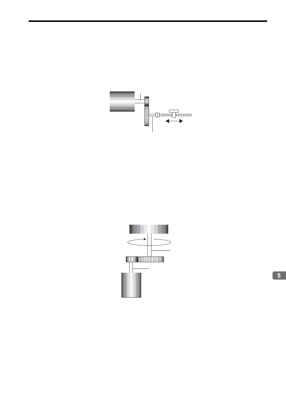
( 1 ) Parameter Setting Example Using Ball Screw
• Machine specifications: Ball screw axis rotates 5 times for each 7 rotations of the motor axis (Refer to the follow-
ing figure.)
• Reference unit: 0.001 mm
To move the workpiece 0.001 mm for 1 reference unit input under the conditions outlined above, i.e., for 1 reference
unit = 1 output unit, make the following settings for fixed parameters 6, 8, and 9.
• Fixed Parameter 6: Travel Distance per Machine Rotation = 6 mm/0.001 mm = 6000 (reference units)
• Fixed Parameter 8: Servo Motor Gear Ratio = m = 7
• Fixed Parameter 9: Machine Gear Ratio = n = 5
Set the SERVOPACK gear ratio to 1:1.
( 2 ) Parameter Setting Example Using Rotating Table
• Machine specifications: Rotating table axis rotates 10 times for each 30 rotations of the motor axis (Refer to the
following figure.)
• Reference unit: 0.1
°
To rotate the table 0.1
° for 1 reference unit input under the conditions outlined above, i.e., for 1 reference unit = 1 out-
put unit, make the following settings for fixed parameters 6, 8, and 9.
• Fixed Parameter 6: Travel Distance per Machine Rotation = 360
°/0.1° = 3600 (reference units)
• Fixed Parameter 8: Servo Motor Gear Ratio = m = 30
• Fixed Parameter 9: Machine Gear Ratio = n = 10
The gear ratio for fixed parameters 8 and 9 (m/n) may be constant, e.g., m = 3 and n = 1.
Set the SERVOPACK gear ratio to 1:1.
Ball screw
Workpiece
P (pitch) = 6 mm/rotation
m = 7 rotations
n = 5 rotations
Motor
Workpiece (Rotating table)
360
°/rotation
n = 10 rotations
Motor
m = 30 rotations