5 ) timing charts – Yaskawa MP2000 Series: Built-in SVB or SVB-01 Motion Module User Manual
Page 211
6.2 Motion Command Details
6.2.7 Relative Position Mode (STEP) (Step Mode)
6-50
[ b ] Monitoring Parameters
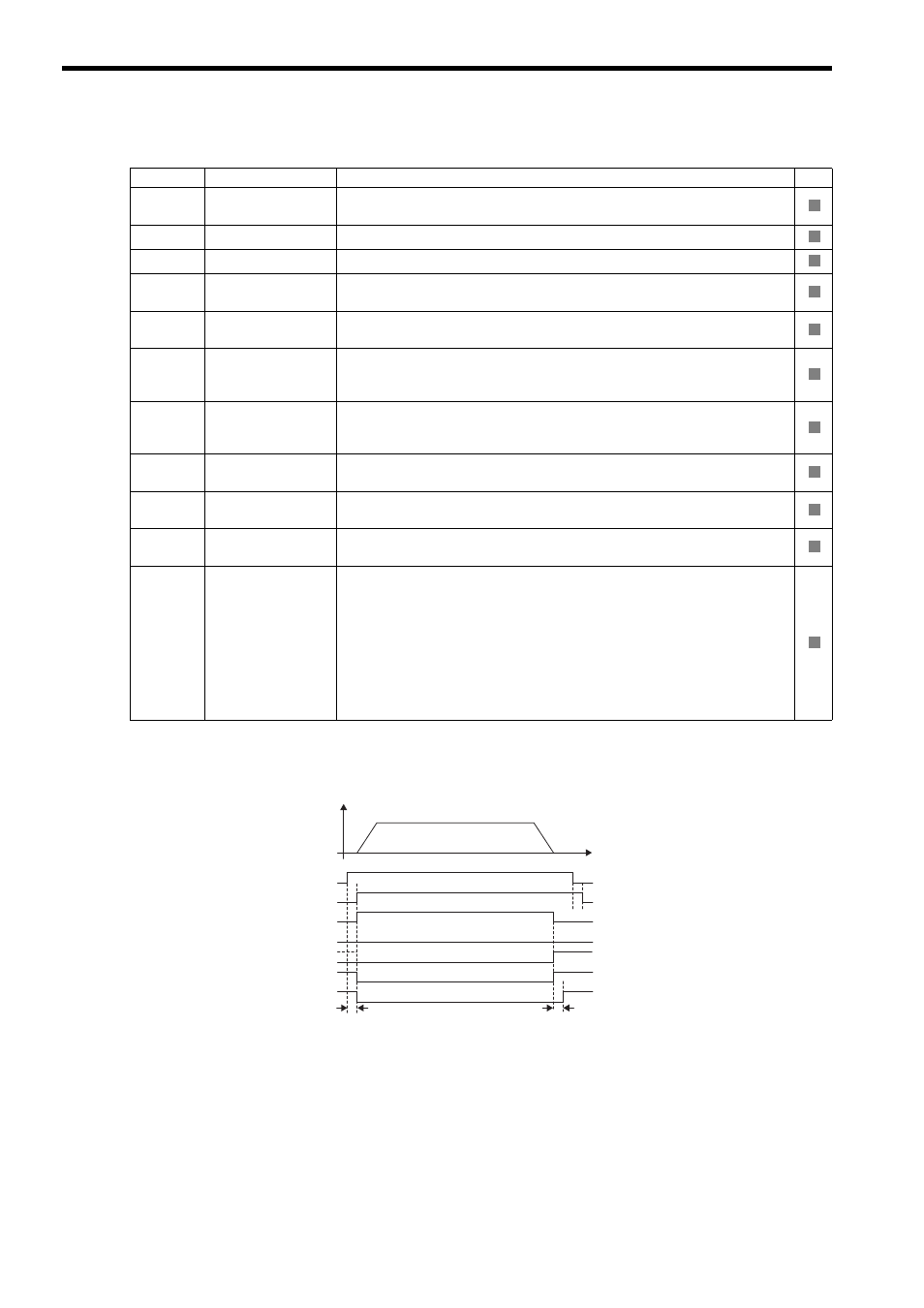
( 5 ) Timing Charts
[ a ] Normal Execution
Parameter
Name
Monitor Contents
SVR
IW
00
Bit 1
Running (At Servo
ON)
Indicates the Servo ON status.
1: Power supplied to Servomotor, 0: Power not supplied to Servomotor
IL
02
Warning
Stores the most current warning.
IL
04
Alarm
Stores the most current alarm.
IW
08
Motion Command
Response Code
Indicates the motion command that is being executed.
The response code is 8 during STEP command execution.
IW
09
Bit 0
Command Execu-
tion Flag
The Command Execution Flag bit will turn ON during STEP command execution
and then turn OFF when STEP command execution has been completed.
IW
09
Bit 1
Command Hold
Completed
Turns ON when a deceleration to a stop has been completed as the result of setting
the Holds a Command (OW
09, Bit1) bit to 1 during STEP command execution
(IW
08 = 8).
IW
09
Bit 3
Command Error
Completed Status
Turns ON if an error occurs during STEP command execution.
The axis will decelerate to a stop if it is moving. Turns OFF when another command
is executed.
IW
09
Bit 8
Command Execu-
tion Completed
Turns ON when STEP command execution has been completed.
IW
0C
Bit 0
Discharging
Completed
Turns ON when pulse distribution has been completed for the move command.
Turns OFF during execution of a move command.
IW
0C
Bit 1
Positioning Com-
pleted
Turns ON when pulse distribution has been completed and the current position is
within the Width of Positioning Completion. OFF in all other cases.
IW
0C
Bit 3
NEAR Position
The operation depends on the setting of the NEAR Signal Output Width (setting
parameter OL
20).
OL
20 = 0: Turns ON when pulse distribution has been completed (DEN =
ON). Otherwise, it turns OFF.
OL
20
≠
0: Turns ON when
the absolute value of the difference between
MPOS (IL
12) and APOS (IL
16) is less than the NEAR
Signal Output Width even if pulse distribution has not been com-
pleted.
OFF in all other cases.
R
R
R
R
R
R
R
R
R
R
R
OW
08 = 8 (STEP)
IW
08 = 8 (STEP)
IW
09, bit 0 (BUSY)
Undefined length of time
IW
09, bit 8 (COMPLETE)
IW
09, bit 3 (FAIL)
IW
0C, bit 0 (DEN)
IW
0C, bit 1 (POSCOMP)
1 scan