24 phase references (phase), Caution, 1 ) executing/operating procedure – Yaskawa MP2000 Series: Built-in SVB or SVB-01 Motion Module User Manual
Page 250
6.2 Motion Command Details
6.2.24 Phase References (PHASE)
6-89
Motion Commands
6.2.24 Phase References (PHASE)
The PHASE command is used for the synchronized operation of multiple axes under phase control mode, using the
specified speed, phase bias, and speed compensation value.
For SVR, the position data and the feedback speed can be monitored.
Speed feed forward compensation cannot be used for the SGD-N or SGDB-N SERVOPACK, so the PHASE com-
mand cannot be used.
When using an SGDV SERVOPACK, the torque limit can be set and changed during SERVOPACK operation. For
details, refer to Setting and Changing Torque Limit during SGDV SERVOPACK Operations of 4.4.2 ( 12 ).
Precautions when using SGDV SERVOPACKs of
Σ-V series
( 1 ) Executing/Operating Procedure
1.
Check to see if all the following conditions are satisfied.
2.
Set the following motion setting parameters.
Speed Reference Setting: OL
10
Filter Type Selection: OW
03, bits 8 to B
Speed Loop P/PI Switch: OW
01
Phase Correction Setting: OL
28
Speed Compensation: OW
31
3.
Set OW
08 to 25 to execute the PHASE motion command.
Synchronized operation using phase control will start.
IW
08 will be 25 during the execution.
4.
Execute another motion command to cancel the phase control mode.
R
If you use the SVB Module to synchronously operate more than one axis as electronic shafts, make sure that
the command resolution is the same for all of the axes.
Example:
If you use a SERVOPACK with a 17-bit encoder together with a SERVOPACK with a 20-bit encoder to con-
trol more than one axis, change the electronic gear ratio of the SERVOPACK with the 20-bit encoder so that
it operates as a 17-bit encoder.
If using the utility functions to adjust the
Σ-V series of SERVOPACKs when the model-following control is
enabled (Pn140.0=1), the SERVOPACK cannot be properly controlled by phase references. When using
phase references, change the settings to the following values.
• Set the model-following control to disabled (Pn140.0=0).
• When using the utility functions for adjustment, select the following modes.
• Advanced Autotuning and Advanced Autotuning by References: Mode=1
• One-parameter Tuning: Tuning mode=0 or 1
CAUTION
No.
Execution Conditions
Confirmation Method
1
There are no alarms.
Both IL
02 and IL
04 are 0.
2
The Servo ON condition.
IW
00, bit 1 is ON.
3
Motion command execution has been completed.
IW
08 is 0 and IW
09, bit 0 is OFF.
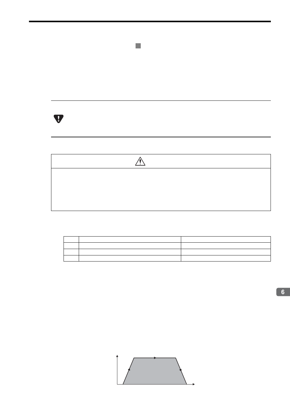
PHASE Operating Pattern
0
Speed (%)
Time (t)
Position