Yaskawa MP2000 Series: Built-in SVB or SVB-01 Motion Module User Manual
Page 397
10.4 Motion Parameter Details
10.4.2 Setting Parameter List
10-33
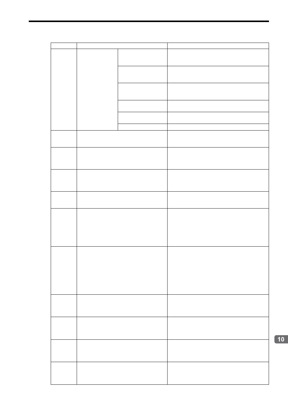
Settings for Connecting Inverters
OW
16
Multi-function
Terminal Output
(Optional)
Bit 0: Contact Output
(MZ-M2) (MA-MB)
0: OFF, 1: ON
Outputs to terminals M1-M2 for Varispeed G7 and F7,
Outputs to terminals MA-MB for VSminiV7
Bit 1: PHC1 Output
(Contact P1-PC)
0: OFF, 1: ON
Outputs to terminals P1-PC for Varispeed G7 and F7, and
VSminiV7.
Bit 2: PHC2 Output
(Contact P2-PC)
0: OFF, 1: ON
Outputs to terminals P2-PC for Varispeed G7 and F7, and
VSminiV7.
Bit 3: PHC3 Output
(Contact P3-C4)
0: OFF. 1: ON
Outputs to terminals P3-C3 for Varispeed G7
Bit 4: PHC4 Output
(Contact P4-C4)
0: OFF, 1: ON
Outputs to terminals P4-C4 for Varispeed G7
Bits 5 to F
Reserved by the system
OW
17
to
OW
31
−
Reserved by the system
OW
32
Inverter Alarm Monitor Number
Setting range: 0 to 3 for Varispeed G7 and F7, 0 or 1 for
VSminiV7
Set the alarm history number for the command Alarm
History Monitor.
OW
33
Auxiliary Inverter Alarm Monitor Number
Setting range: 0 to 3 for Varispeed G7 and F7, 0 or 1 for
VSminiV7
Set the alarm history number for the subcommand Alarm
History Monitor.
OW
34
to
OW
3B
−
Reserved by the system
OW
3C
Inverter User Constant Number
Setting range: 0 to FFFFH
Sets the leading number of the user constants to read by
executing the command Read User Constant, or set the
leading number of the user constants to write by execut-
ing the command Write User Constant.
Set the register number used for MEMOBUS
communications.
OW
3D
Inverter User Constant Number Size
Setting range: 1 to 4 (word)
Sets the size of the user constant to read by executing the
command Read User Constant, or set the size of the user
constant to be write by executing the command Write
User Constant, in words.
Each inverter user constant is composed of one word.
Therefore, setting the Inverter User Constant Number
Size enables the reading or writing of data of 1 to 4 con-
secutive words at once.
OW
3E
Inverter User Constant
Set Point 1
Setting range: 0 to 65535
Sets the data to write for the command Write User Con-
stant.
Valid when Inverter User Constant Number Size = 1 to 4
OW
3F
Inverter User Constant
Set Point 2
Setting range: 0 to 65535
Sets the data to write for the command Write User Con-
stant.
Valid when Inverter User Constant Number Size = 2 to 4.
OW
40
Inverter User Constant
Set Point 3
Setting range: 0 to 65535
Sets the data to write for the command Write User Con-
stant.
Valid when Inverter User Constant Number Size = 3 or 4.
OW
41
Inverter User Constant
Set Point 4
Setting range: 0 to 65535
Sets the data to write for the command Write User Con-
stant.
Valid when Inverter User Constant Number Size = 4.
Register No.
Name
Contents