7 precautions for the use of sgdv servopacks, 1 software limit settings, 2 when the tuning-less function is enabled – Yaskawa MP2000 Series: Built-in SVB or SVB-01 Motion Module User Manual
Page 442: 3 saving the parameter bank data, 1 ) gain related settings, 2 ) gain-related motion commands, 3 ) gain switching
11.7 Precautions for the Use of SGDV SERVOPACKs
11.7.1 Software Limit Settings
11-27
Utility Functions
11.7 Precautions for the Use of SGDV SERVOPACKs
11.7.1 Software Limit Settings
Use the software limit setting of the Machine Controller, not that of the SGDV SERVOPACK.
11.7.2 When the Tuning-less Function is Enabled
In SGDV SERVOPACKs, Pn170.0 is set to 1 (default setting) and the tuning-less function is enabled. Any actions
related to the settings of gain-related parameters are disabled.
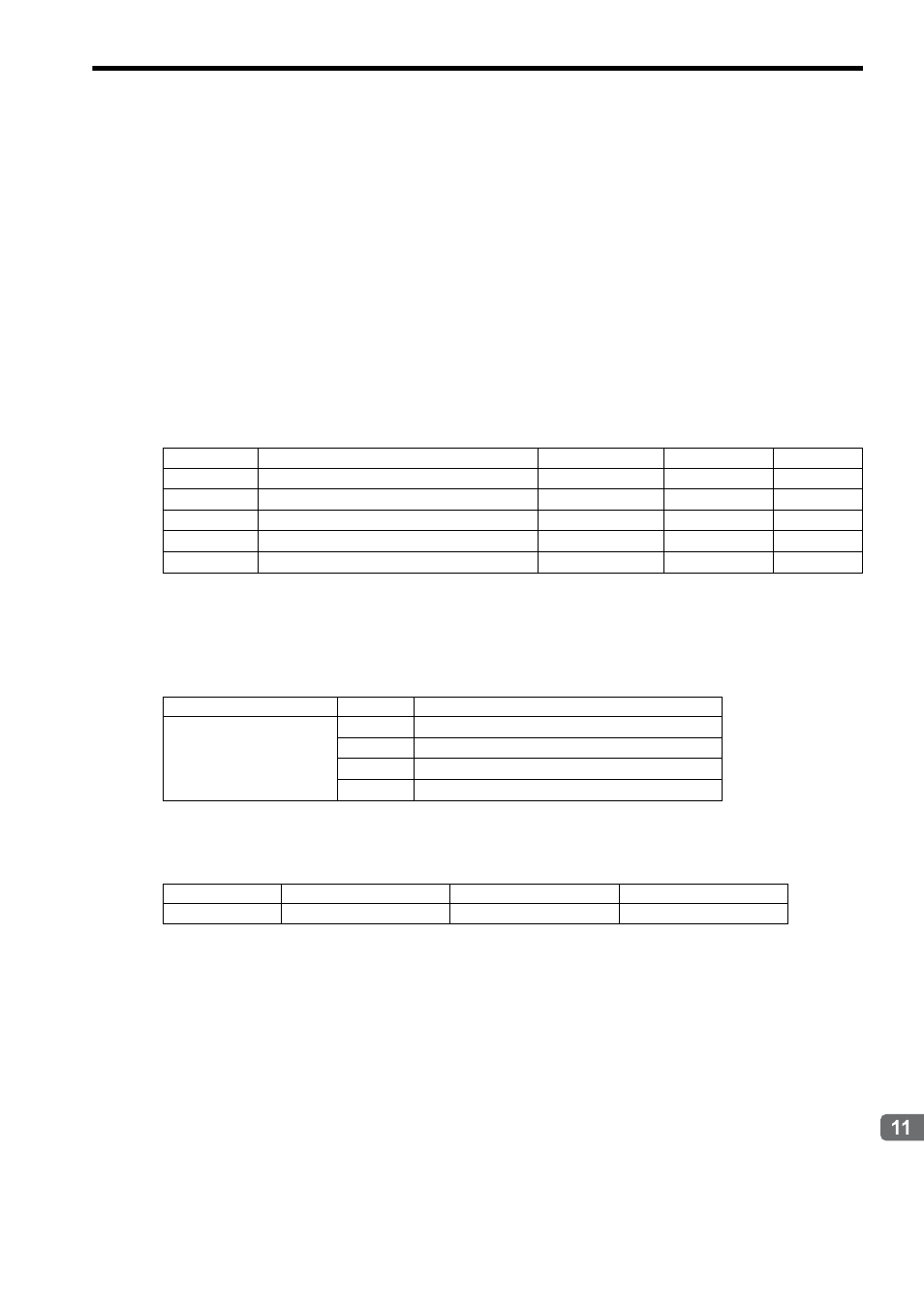
( 1 ) Gain Related Settings
The related servo parameters are changed when the User Constants Self-Writing Function of Function Selection Flag 1
(fixed parameter) is enabled and the following parameters are changed. The settings, however, do not affect actual
operations.
( 2 ) Gain-related Motion Commands
The related servo parameters are changed in accordance with the results obtained by executing the following motion
commands.
The settings, however, do not affect actual operations.
( 3 ) Gain Switching
Even if the setting for Mode Setting 1of the Gain Switch is changed, this setting does not affect actual operations.
11.7.3 Saving the Parameter Bank Data
When using the Parameter Bank function, the Bank data (Pn920 to Pn95F) is not saved in the nonvolatile memory.
These parameters must always be reset if using a MECHATROLINK network between the Motion Controller and the
SERVOPACK.
If these parameters are set to 0 and have not been changed, the Parameter Bank function operates in accordance with
the minimum value of each parameter.
Register no.
Name
Setting range
Default value
Meaning
OW
2E
Position Loop Gain
0 to 32767
300
1 = 0.1/s
OW
2F
Speed Loop Gain
1 to 2000
40
1 = 1 Hz
OW
30
Speed Feed Forward Amends
0 to 32767
0
1 = 0.01%
OW
32
Position Integration Time Constant
0 to 32767
0
1 = 1 ms
OW
34
Speed Integration Time Constant
15 to 65535
0
1 = 0.01 ms
Register no.
Setting
Meaning
OW
08
14
Change Speed Loop Gain (KVS)
15
Change Position Loop Gain (KPS)
16
Change Feed-forward (KFS)
26
Change Position Loop Integral Time Constant (KIS)
Register no.
Name
Meaning
Remark
OW
01
Mode Setting 1
Bit 4: Gain Switch
0: OFF, 1: ON