7 relative position mode (step) (step mode), 1 ) executing/operating procedure, 2 ) holding – Yaskawa MP2000 Series: Built-in SVB or SVB-01 Motion Module User Manual
Page 209
6.2 Motion Command Details
6.2.7 Relative Position Mode (STEP) (Step Mode)
6-48
6.2.7 Relative Position Mode (STEP) (Step Mode)
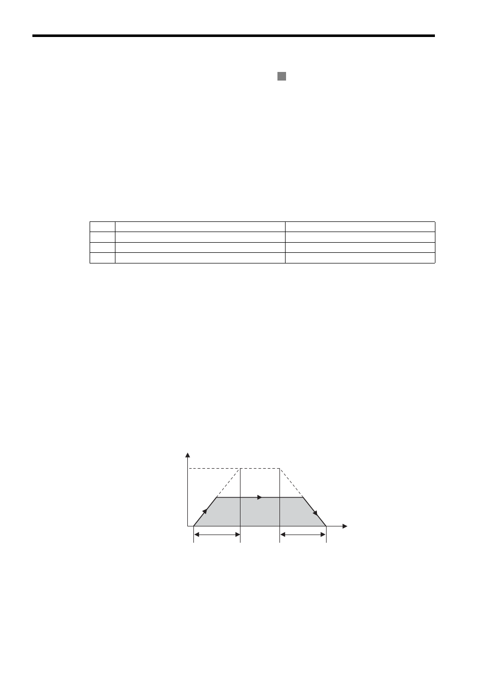
The STEP command executes a positioning for the specified travel direction, moving amount, and travel speed.
Parameters related to acceleration and deceleration are set in advance.
When using an SGDV SERVOPACK, the torque limit can be set and changed during SERVOPACK operation. For
details, refer to Setting and Changing Torque Limit during SGDV SERVOPACK Operations of 4.4.2 ( 12 ).
Also, refer to Precautions of 6.2.1 ( 3 ).
For more information on the maximum allowable value for acceleration and deceleration, refer to Changing the max-
imum value of acceleration and deceleration for SGDV SERVOPACKs of 4.4.2 ( 23 ).
( 1 ) Executing/Operating Procedure
1.
Check to see if all the following conditions are satisfied.
2.
Set the following motion setting parameters.
STEP Travel Distance: OL
44
Moving Direction (JOG/STEP): OW
09, bit 2
Speed Reference Setting: OL
10
Filter Type Selection: OW
03, bits 8 to B
Speed Loop P/PI Switch: OW
01
The speed reference Setting bit OL
10 can be changed during operation.
An override of between 0% to 327.67% can be set for the travel speed.
3.
Set OW
08 to 8 to execute the STEP motion command.
STEP operation will start. IW
08 will be 8 during execution.
IW
0C, bit 3 will turn ON when the axis reaches the target position.
IW
0C, bit 1 will turn ON when the axis reaches the target position and the positioning has been completed.
4.
Set OW
08 to 0 to execute the NOP motion command and then complete the STEP operation.
( 2 ) Holding
Axis travel can be stopped during command execution and then the remaining travel can be restarted. A command is
held by setting the Holds a Command (OW
09, bit 0) to 1.
• Set the Holds a Command bit (OW
09, bit 0) to 1. The axis will decelerate to a stop.
• When the axis has stopped, the Command Hold Completed bit (IW
09, bit 1) will turn ON.
• Turn OFF the Holds a Command bit (OW
09, bit 0).
The command hold status will be cleared and the remaining portion of the positioning will be restarted.
R
No.
Execution Conditions
Confirmation Method
1
There are no alarms.
Both IL
02 and IL
04 are 0.
2
The Servo ON condition.
IW
00, bit 1 is ON.
3
Motion command execution has been completed.
IW
08 is 0 and IW
09, bit 0 is OFF.
Speed (%)
(100%)
0
Time (t)
Travel speed
Rated speed
STEP travel
distance
Straight Line
Acceleration Time
Constat
Straight Line
Deceleration Time
Constant
STEP Operating Pattern