5 troubleshooting motion errors, 1 overview of motion errors – Yaskawa MP2000 Series: Built-in SVB or SVB-01 Motion Module User Manual
Page 475
12.5 Troubleshooting Motion Errors
12.5.1 Overview of Motion Errors
12-32
12.5 Troubleshooting Motion Errors
This section explains the details and corrective actions for errors that occur in motion control functions.
12.5.1 Overview of Motion Errors
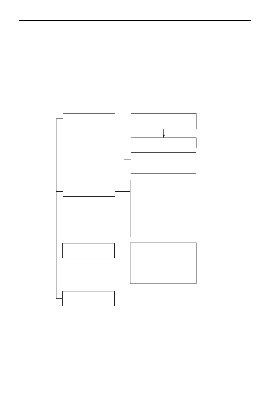
Motion errors in the MP2000-series Machine Controller include axis alarms detected for individual SERVOPACKs.
The failure location can be determined and appropriate corrections can be taken simply by checking the contents of the
Warning (IL
02) and Alarm (IL
04) monitoring parameters.
The motion alarms for the Machine Controller Basic Module’s MECHATROLINK-I or MECHATROLINK-II func-
tionality are shown below.
* 1. Refer to
12.5.2 Motion Error Details and Corrections.
* 2. Refer to
12.5.3 ( 1 ) Servo Driver Status (IW
2C) List.
* 3. Refer to
12.5.3 ( 2 ) Servo Driver Alarm Code (IW
2D).
Warning (IL
02)
Bit 1: Setting Parameter Error
Bit 2: Fixed Parameter Error
Bit 0: Excessive Deviation
Bit 3: Servo Driver Error
Bit 4: Motion Command Set Error
Bit 0: Servo Driver Error
Bit 1: Positive Direction Overtravel
Bit 2: Negative Direction Overtravel
Bit 3: Positive Direction Software Limit
Bit 4: Negative Direction Software Limit
Bit 5: Servo OFF
Servo Driver Alarm Code
∗3
(IW
2D)
Alarm (IL
04)
∗1
Servo Driver Status
∗2
(IW
2C)
Bit 0: Alarm (ALM)
Bit 1: Warning (WARNG)
Bit 2: Command READY (CMDRDY)
Bit 3: Servo ON (SVON)
Bit D: Negative Software Limit (N_SOT)
Parameter Number when Range
Over is Generated (IW
01)
Bit 1E: Motor Type Set Error
Bit 1F: Connected Encoder Type Error