2 setting the zero point for a finite length axis, Caution – Yaskawa MP2000 Series: Built-in SVB or SVB-01 Motion Module User Manual
Page 346
9.3 Absolute Position Detection for Finite Length Axes
9.3.2 Setting the Zero Point for a Finite Length Axis
9-9
Absolute Position Detection
9.3.2 Setting the Zero Point for a Finite Length Axis
This section describes the procedure for setting the zero point (i.e., the absolute zero point or the zero point of the
machine coordinate system) for a finite length axis. It also describes the procedures for storing the zero point offset.
( 1 ) Calculating the Zero Point of the Machine Coordinate System
The Machine Controller calculates the axis position (i.e., current position for the machine coordinate system) as fol-
lows when power is turned ON if an absolute encoder is used for positioning.
Current position for the machine coordinate system (monitoring parameter IL
10
*1
or IL
16
*1
) =
Encoder position when servo power is turned ON
*2
+ Zero Point Position in Machine Coordinate System Off-
set (setting parameter OL
48)
To set the current position of the machine coordinate system as the zero position, set OL
48 to the difference
between OL
48 and IL
10 (or IL
16).
* 1. Use IL
10 to select a positive value for the reference position for the machine coordinates, and use IL
16 to
make the current position of the machine coordinates into a positive position.
* 2. The encoder position when servo power is turned ON is as follows: Multiturn data
× Number of encoder pulses +
initial increment pulses. Refer to your SERVOPACK manual for information on the initial increment pulses.
Example: IL
10 = 10,000 and OL
48 = 100
Set the encoder position when servo power is turned ON to a negative value as shown below.
OL
48 - IL
10 = 100 - 10000
= - 9900
Set OL
48 to -9900 to make the current position in the machine coordinate system the zero point.
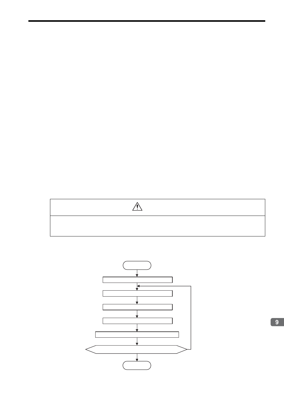
( 2 ) Setting the Zero Point of the Machine Coordinate System
Set the zero point after initializing the absolute encoder to set the zero point of the machine coordinate system and to
create the machine coordinate system. The following illustration shows the procedure for setting the zero point for a
finite length axis.
OL
48 is always valid for a finite length axis. Do not change the Zero Point Position in Machine Coordi-
nate System Offset (OL
48) during the operation of a machine with a finite length axis. Otherwise the
machine may be damaged or an accident may occur.
CAUTION
Repeat for every axis.
Start
End
YES
NO
Servo ON
JOG to move close to the zero point.
STEP to move to the zero point.
Set OL
48 to OL
48 - IL
10.
Use the ZSET command to set the zero point.
Has the setting for the required axis been completed?