Assigning virtual links, Figure 7 – Brocade Network OS NETCONF Operations Guide v4.1.1 User Manual
Page 562
530
Network OS NETCONF Operations Guide
53-1003231-02
Performing basic OSPF configuration
34
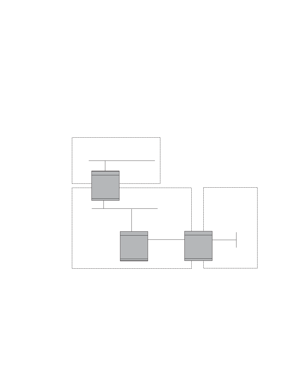
Assigning virtual links
All ABRs must have either a direct or indirect link to the OSPF backbone area (0.0.0.0 or 0). If an
ABR does not have a physical link to the area backbone, the ABR can configure a virtual link to
another router within the same area, which has a physical connection to the backbone area. Refer
to the Network OS Administrator’s Guide for details.
shows an OSPF area border router, Device A, that is cut off from the backbone area (area
0). To provide backbone access to Device A, you can add a virtual link between Device A and Device
C using area 1 as a transit area. To configure the virtual link, you define the link on the router that
is at each end of the link. No configuration for the virtual link is required on the routers in the
transit area.
FIGURE 7
Defining OSPF virtual links within a network
To define the virtual link on Device A, establish a NETCONF session with Device A, and issue the
following
and area 1). For the transition area (area 1), the node element also includes the
transition area to the backbone area.
OSPF Area 0
OSPF Area 1
“transit area”
OSPF Area 2
Device C
Router ID 209.157.22.1
Device B
Device A
Router ID 10.0.0.1