System architecture, System architecture -3 – Carrier Access Access Navigator User Manual
Page 51
Access Navigator - Release 1.8
August 2003
3-3
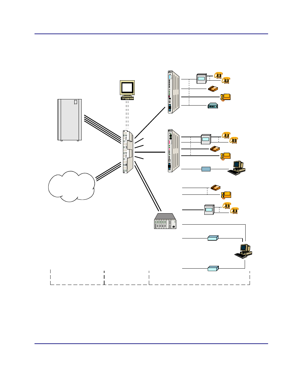
Access Navigator / GR-303 + Data Host
System Architecture
System Architecture
Figure 3-2. Access Navigator / GR-303 + Data Host Architecture
Switch with
GR-303
Switch
DS1s
Groom
DS1s
DCS Voice
and Data
GR-303
Voice
Access
Navigator
Internet, Data,
Private and
Special Services
Drop
DS1s
24
Lines
PBX
Key System
Modem
Fax
Stations
Access Bank I
Voice
A CCESS BANK I
Tip & Rin g
-48Vd c
Return
Groun d
T1
Fr aming
O utput
M onitor
In put
M onitor
A larm
C ut-Off
T1
Test
Network
L oopback
N ormal
Normal
Normal
Self
Test
Normal
Remote
Status
Key System
Fax
V.35, T1
or DSL
Router
Ethernet
PBX
Stations
Access Bank II
Voice
and
Data
Voice
Lines
A CCESS BANK II
Ti p & Rin g
-48Vdc
Return
Groun d
T1
Span 1
T 1 Test 2
T1 Test 1
T1
Span 2
V.35
DCE
V.35
S tatus
RS232
Data
DDS
ISDN BRI
T1 Drop
V.35
Adit 600
Key System
Fax
Router Ethernet
PBX
Stations
RS232
VoIP
T1 Drop
Modem
FXS/FXO
10/100BaseT
Switch Center
Customer Premises
Co-location
Voice
and
Data
ADIT 600
Remote
Management
RS-232
Ethernet