Wire alarm input connector, Wire alarm input connector -32 – Carrier Access Access Navigator User Manual
Page 136
6-32
August 2003
Access Navigator - Release 1.8
Electrical Installation
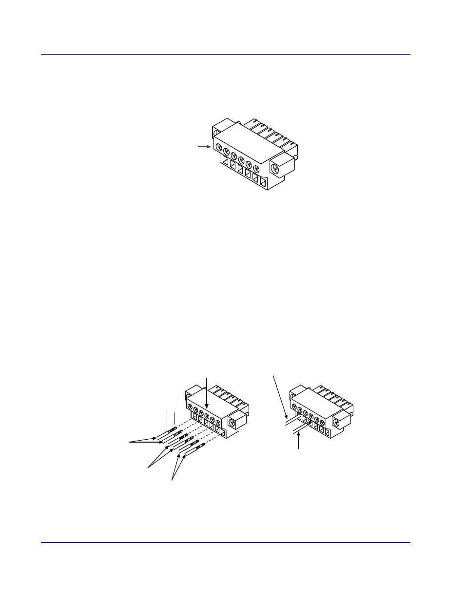
Wire Alarm Input Connector
Wire Alarm Input Connector
1. Open package containing alarm input connector.
Figure 6-19. Alarm Input Connector
2. Refer to Figure 6-20 and Figure 6-21 when wiring connector to facility alarm system.
3. Use volt-ohm meter to ensure that no voltage is present on any of the wires from the facility alarm
system (see Figure 6-21).
4. Strip the wires so that 5/16 inch of bare wire is exposed (see Figure 6-20).
5. Orient the alarm output connector as shown in Figure 6-20.
6. Insert wire into bottom opening, then tighten screw above to clamp wire in place.
7. Ensure that no bare wire shows after the wires are installed.
8. Connect cable shield to Access Navigator chassis ground or to its equipment rack. Do not ground
both ends of shield.
Figure 6-20. Alarm Input Connector Wiring
Set screws
may be on
front or top
Alarm 1
(Pins 1 & 2)
Alarm 2
(Pins 3 & 4)
Alarm 3
(Pins 5 & 6)
Strip off
insulation
5/16 inch
This wire is connected
correctly
This wire is connected
incorrectly (bare wire
is showing)
Tighten screws
to clamp wires