Wire alarm output connector, Wire alarm output connector -28 – Carrier Access Access Navigator User Manual
Page 132
6-28
August 2003
Access Navigator - Release 1.8
Electrical Installation
Wire Alarm Output Connector
Wire Alarm Output Connector
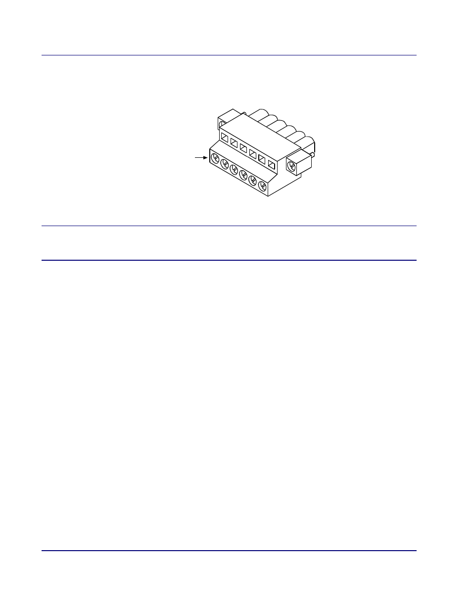
1. Open package containing alarm output connector (see Figure 6-15).
Figure 6-15. Alarm Output Connector
NOTE:
Figure 6-16 shows the alarm output connector wiring to a typical alarm interface
circuit. The alarm relay output provides normally open contacts. There is no voltage
present on these contacts until they are energized by the external alarm system.
2. Refer Figure 6-16 and Figure 6-17 when wiring connector to facility alarm system.
3. Use volt-ohm meter to ensure that no voltage is present on any of the wires going to the facility
alarm system (see Figure 6-16).
4. Strip the wires so that 5/16 inch of bare wire is exposed (see Figure 6-17).
5. Orient the alarm output connector as shown in Figure 6-17.
6. Insert wire into top opening, then tighten screw below to clamp wire in place.
7. Ensure that no bare wire shows after the wires are installed.
Set screws
may be on
front or bottom