Verify alarm output connections, Verify alarm output connections -45, Caution – Carrier Access Access Navigator User Manual
Page 149
Access Navigator - Release 1.8
August 2003
6-45
Electrical
Installation
Verify Alarm Output Connections
Verify Alarm Output Connections
CAUTION!
M
AXIMUM
RELAY
CONTACT
RATING
IS
1 A
MPERE
@ 110 V AC
OR
DC.
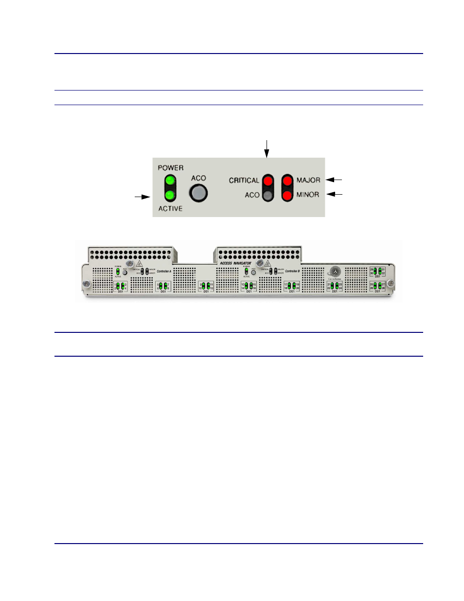
Figure 6-30. Location of Alarm Status Indicators
NOTE:
If alarm indications are not correct, refer to Diagnostics & Troubleshooting on
.
1. Verify critical output alarm functions as follows.
•
Enter the following command to simulate critical alarm.
set alarms critical on
Requirement:
Critical alarm relay output contacts close (see Figure 6-16 on
).
Requirement:
Active Controller card Critical Alarm indicator lights (Figure 6-30).
•
Enter the following command to turn off critical alarm.
set alarms critical off
Requirement:
Critical alarm relay output contacts open.
Requirement:
Active Controller card Critical Alarm indicator goes off.
Controller ’A’ Indicators
Controller ’B’ Indicators
Minor Alarm
Active
Controller
Major Alarm
Critical Alarm