Establishment of an irf fabric, Topology and connections of an irf fabric, Figure 1-1 – H3C Technologies H3C S3600 Series Switches User Manual
Page 791

1-2
Figure 1-1 IRF networking
IP network
IRF
IP network
IRF link
Equals
Master
Slave
Slave
Establishment of an IRF Fabric
Topology and connections of an IRF fabric
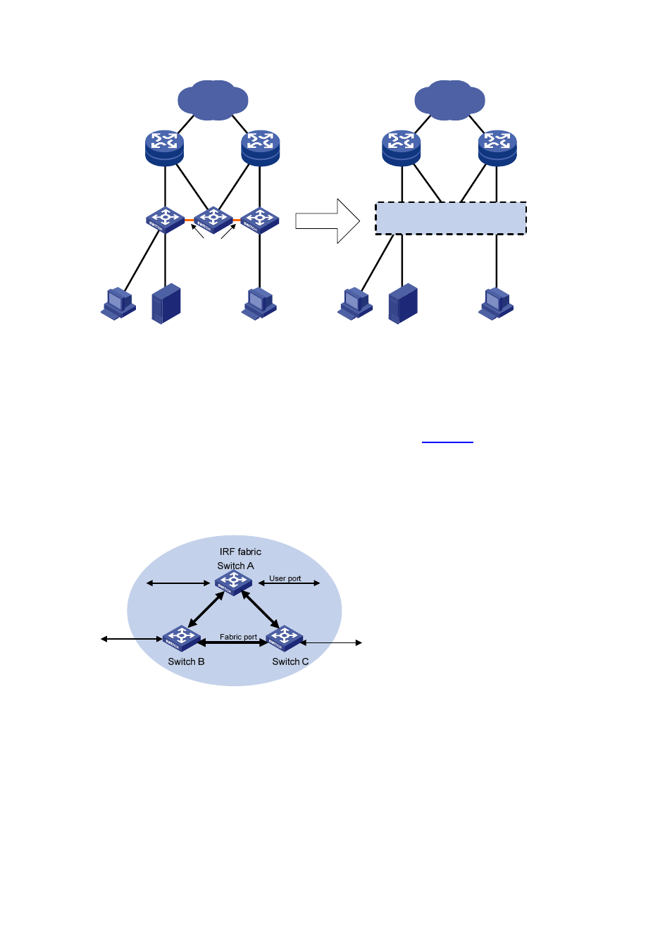
An IRF fabric typically has a ring topology structure. As shown in
, each switch has two ports
connected with two other switches in the fabric. These two ports are called fabric ports in general, a left
port and a right port respectively; the other ports, which are available for connections with users or
devices outside the fabric, are called user ports.
Figure 1-2 A schematic diagram of an IRF fabric
A correctly built IRF fabric features the following:
z
Multiple S3600 series switches are interconnected through their fabric ports.
z
Given a switch, its left port is connected to the right port of another switch, and its right port is
connected to the left port of a third one.
