Auto vlan configuration example, Network requirements, Network diagram – H3C Technologies H3C S3600 Series Switches User Manual
Page 549: Configuration procedure, Auto vlan configuration, Example

2-33
# Configure the domain name of the HWTACACS scheme to hwtac.
[Sysname] domain hwtacacs
[Sysname-isp-hwtacacs] scheme hwtacacs-scheme hwtac
Auto VLAN Configuration Example
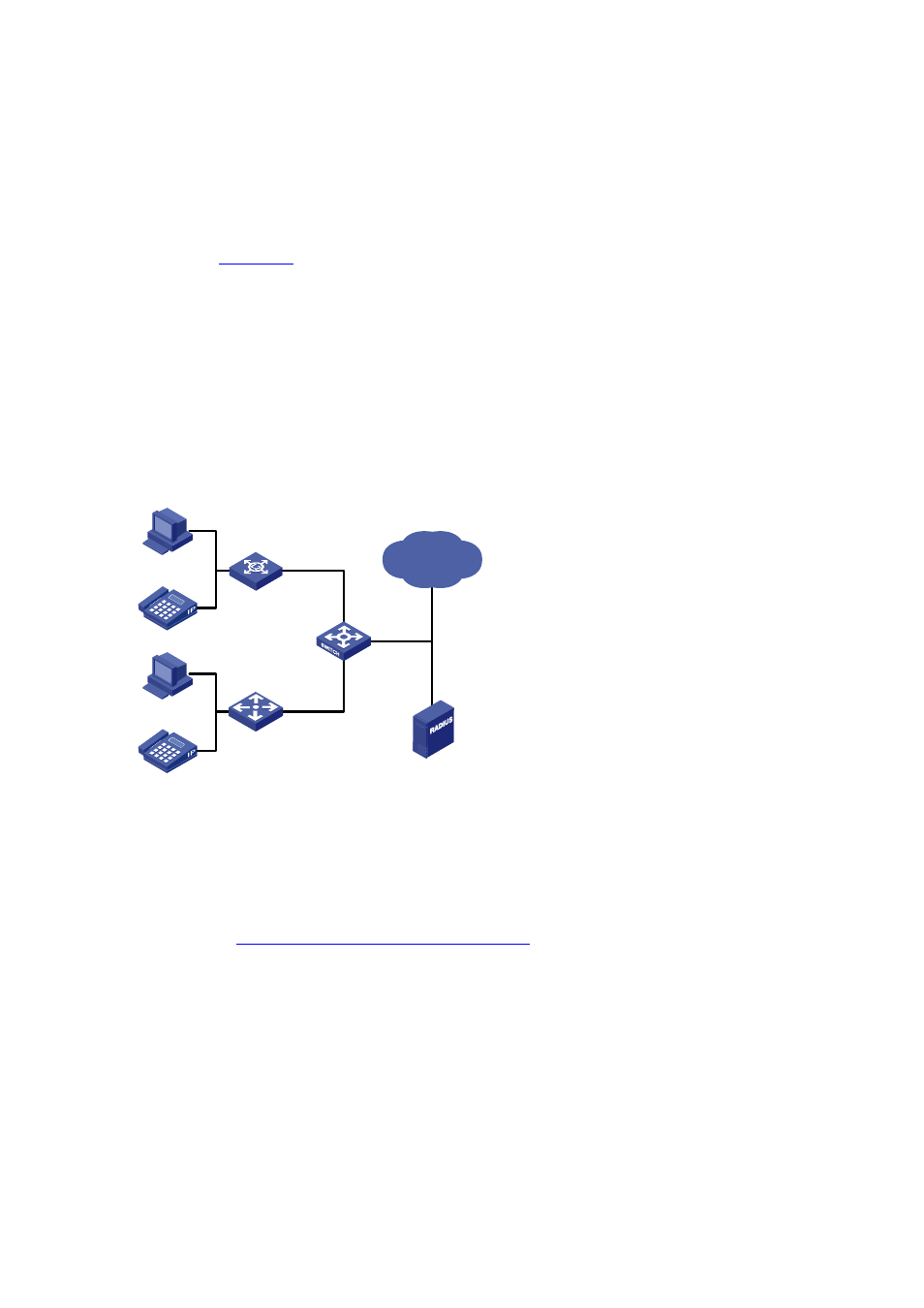
Network requirements
As shown in
, use 802.1X authentication on Ethernet 1/0/1 and Ethernet 1/0/2 to authenticate
users. After a user passes the authentication on a port, the RADIUS server issues a VLAN list to the
switch, which assigns the authentication port to a VLAN that the IP phone needs to access. After that,
the IP phone can access the network. The access control mode is port-based.
z
All users belong to ISP domain abc; the RADIUS scheme is bbb;
z
The RADIUS server is connected to Switch; the IP address of the RADIUS server is 1.1.1.1.
z
The shared key used when Switch and the RADIUS server exchange packets is hello.
Network diagram
Figure 2-5 Network diagram for Auto VLAN configuration
IP network
RADIUS server
Switch
Hub
PC
IP phone
L2 switch
PC
IP phone
Eth1/0/1
Eth1/0/2
Configuration procedure
z
Configuration on the RADIUS server
The configuration may vary on different RADIUS servers. Configure VLAN lists on the RADIUS server
Configuring dynamic VLAN list assignment
.
z
Configuration on 802.1x clients
The configuration may vary on different 802.1x clients. Configure 802.1x clients by referring to related
802.1x client configuration guides.
z
Configuration on the authentication switch
# Configure the authentication scheme.
[Switch] radius scheme bbb
[Switch-radius-bbb] primary authentication 1.1.1.1
[Switch-radius-bbb] key authentication hello
[Switch-radius-bbb] primary accounting 1.1.1.1
[Switch-radius-bbb] key accounting hello
