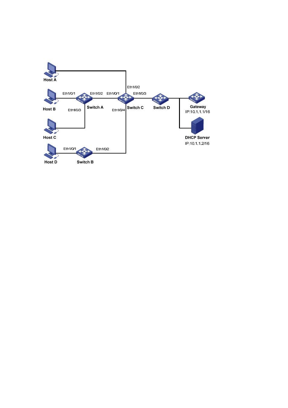
Network diagram, Configuration procedure – H3C Technologies H3C S3600 Series Switches User Manual
Page 629

5-8
Enable MFF on Switch A, Switch B and Switch C respectively, implementing Layer 2 isolation and Layer
3 communication among the hosts through Gateway.
Network diagram
Figure 5-2 MFF network diagram
Configuration procedure
1) Configure
Gateway.
# Configure the VLAN interface IP address of the gateway.
[Gateway] interface Vlan-interface 1
[Gateway-Vlan-interface1] ip address 10.1.1.1 16
2) Configure the DHCP server
[DHCPServer] dhcp enable
[DHCPServer] dhcp server ip-pool 1
[DHCPServer-dhcp-poop-1] network 10.1.1.0 mask 255.255.0.0
[DHCPServer-dhcp-poop-1] gateway-list 10.1.1.1
[DHCPServer-dhcp-poop-1] quit
[DHCPServer]interface Vlan-interface 1
[DHCPServer-Vlan-interface1] ip address 10.1.1.2 16
3) Configure Switch A.
# Enable DHCP snooping.
[SwitchA] dhcp-snooping
# Enable ARP intrusion detection in VLAN 1.
[SwitchA] vlan 1
[SwitchA-vlan1] arp detection enable
# Enable MFF.
[SwitchA-vlan-1] arp mac-forced-forwarding auto
