Network requirements, Network diagram, Configuration procedure – H3C Technologies H3C S3600 Series Switches User Manual
Page 617

3-4
[Switch] interface Vlan-interface 3
[Switch-Vlan-interface3] ip address 192.168.0.27 24
[Switch-Vlan-interface3] quit
# Configure the IP address of VLAN-interface 4 to be 192.168.1.27/24.
[Switch] interface Vlan-interface 4
[Switch-Vlan-interface4] ip address 192.168.1.27 24
[Switch-Vlan-interface4] quit
# Enter VLAN-interface 3 view, and enable common proxy ARP on it.
[Switch] interface Vlan-interface 3
[Switch-Vlan-interface3] arp proxy enable
[Switch-Vlan-interface3] quit
# Enter VLAN-interface 4 view, and enable common proxy ARP on it.
[Switch] interface Vlan-interface 4
[Switch-Vlan-interface4] arp proxy enable
[Switch-Vlan-interface4] quit
Local Proxy ARP Configuration in Port Isolation Application
Network requirements
z
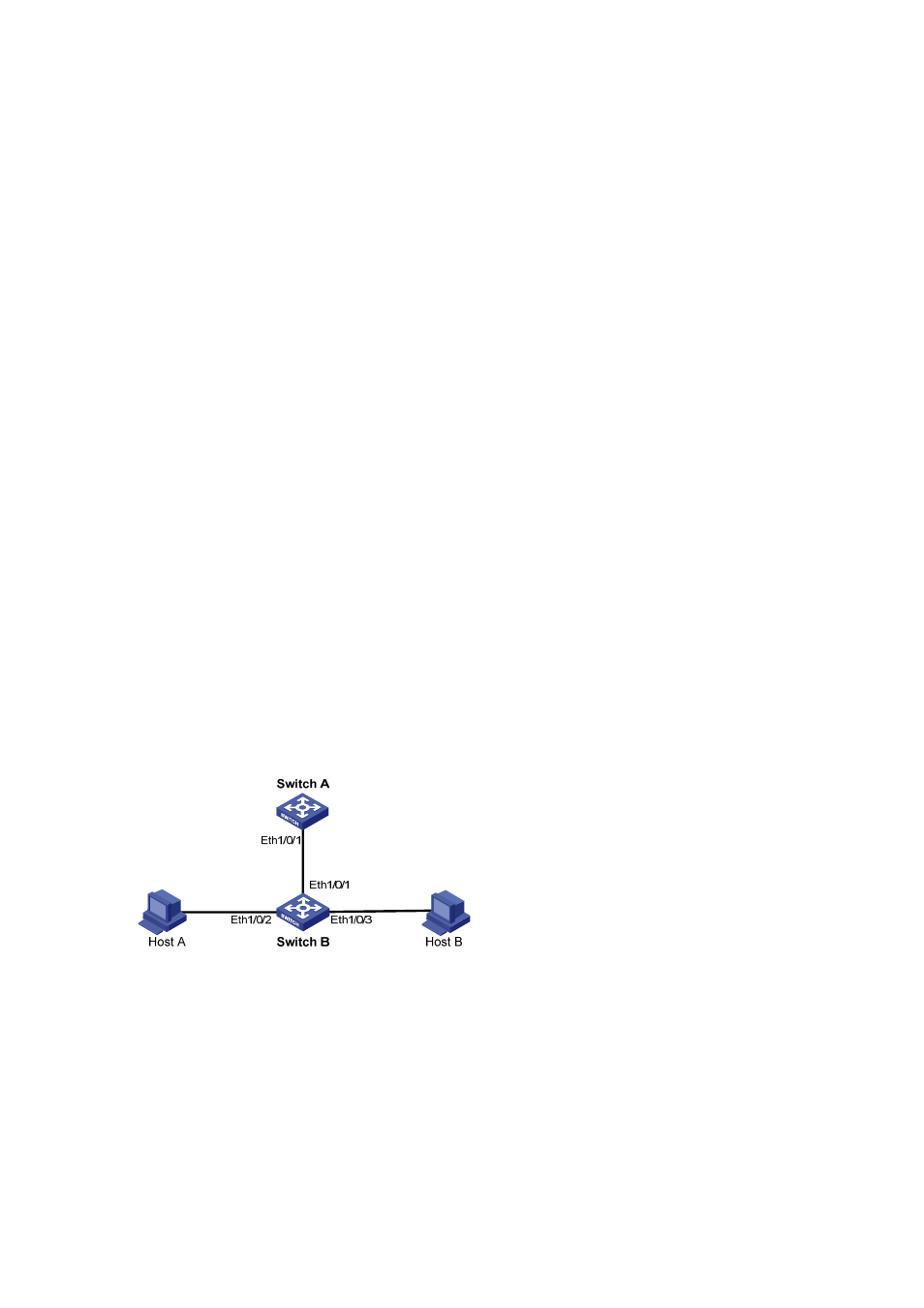
Switch A (a S3600 series Ethernet switch) is connected to Switch B through Ethernet 1/0/1.
z
Ethernet 1/0/2 and Ethernet 1/0/3 on Switch B belong to VLAN 1, and are connected to Host A and
Host B respectively.
z
Host A and Host B isolated at Layer 2 can communicate at Layer 3 through Switch A.
Network diagram
Figure 3-4 Network diagram for local proxy ARP configuration in port isolation application
Configuration procedure
1) Configure Switch B
# Add Ethernet 1/0/2 and Ethernet 1/0/3 into an isolation group, disabling Host A and Host B from
communicating with each other at Layer 2.
For details about port isolation, refer to the part discussing port isolation.
[SwitchB] interface Ethernet 1/0/2
[SwitchB-Ethernet1/0/2] port isolate
