Vlan mapping configuration example, Network requirements, Network diagram – H3C Technologies H3C S3600 Series Switches User Manual
Page 759: Configuration procedure

1-29
VLAN Mapping Configuration Example
Network requirements
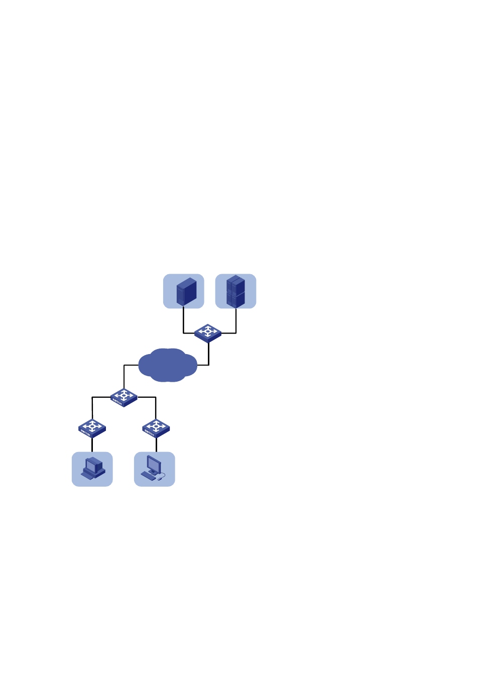
Two customer networks are connected to the public network through Switch A and Switch B. Configure
the VLAN mapping function on the switches to enable the hosts on the two customer networks to
communicate through public network VLANs.
z
Switch A provides network access for terminal devices in VLAN 100 and VLAN 200 through
Ethernet 1/0/11 and Ethernet 1/0/12. On the other side of the public network, Switch B provides
network access for servers in VLAN 100 and VLAN 200 through Ethernet 1/0/15 and Ethernet
1/0/16.
z
Switch A provides access to the public network through Ethernet 1/0/10 and Switch B provides
access to the public network through Ethernet 1/0/17.
Configure the switches to have packets of VLAN 100 and packets of VLAN 200 transmitted in VLAN 500
and VLAN 600 across the public network.
Network diagram
Figure 1-11 Network diagram for VLAN mapping configuration
Eth1/0/11
Eth1/0/12
Eth1/0/10
VLAN100
VLAN200
VLAN100
VLAN200
SwitchA
SwitchB
Eth1/0/15
Eth1/0/16
Eth1/0/17
Public Network
VLAN500/600
Configuration procedure
# Create customer VLANs VLAN 100 and VLAN 200 and service VLANs VLAN 500 and VLAN 600 on
Switch A.
[SwitchA] vlan 100
[SwitchA-vlan100] quit
[SwitchA] vlan 200
[SwitchA-vlan200] quit
