Ospf configuration examples, Configuring dr/bdr election, Network requirements – H3C Technologies H3C S3600 Series Switches User Manual
Page 352: Network diagram, Configuration procedure

4-25
To do...
Use the command...
Remarks
Display OSPF virtual links
display ospf [ process-id ] vlink
Display OSPF request list
display ospf [ process-id ] request-queue
Display OSPF retransmission list
display ospf [ process-id ] retrans-queue
Display the information about
OSPF ABR and ASBR
display ospf [ process-id ] abr-asbr
Display OSPF interface
information
display ospf [ process-id ] interface
interface-type interface-number
Display OSPF errors
display ospf [ process-id ] error
Display OSPF ASBR
summarization information
display ospf [ process-id ] asbr-summary
[ ip-address mask ]
Reset OSPF process(es)
reset ospf { all | process-id }
Clear the statistics of one or all
OSPF processes
reset ospf statistics { all | process-id }
Available in
user view
OSPF Configuration Examples
Configuring DR/BDR Election
Network requirements
Use OSPF to realize interconnection between devices in a broadcast network. Devices with higher
performance should become the DR and BDR to improve network performance. Devices with lower
performance are forbidden to take part in DB/BDR election.
Based on the customer requirements and networking environment, assign proper priorities to
interfaces.
Network diagram
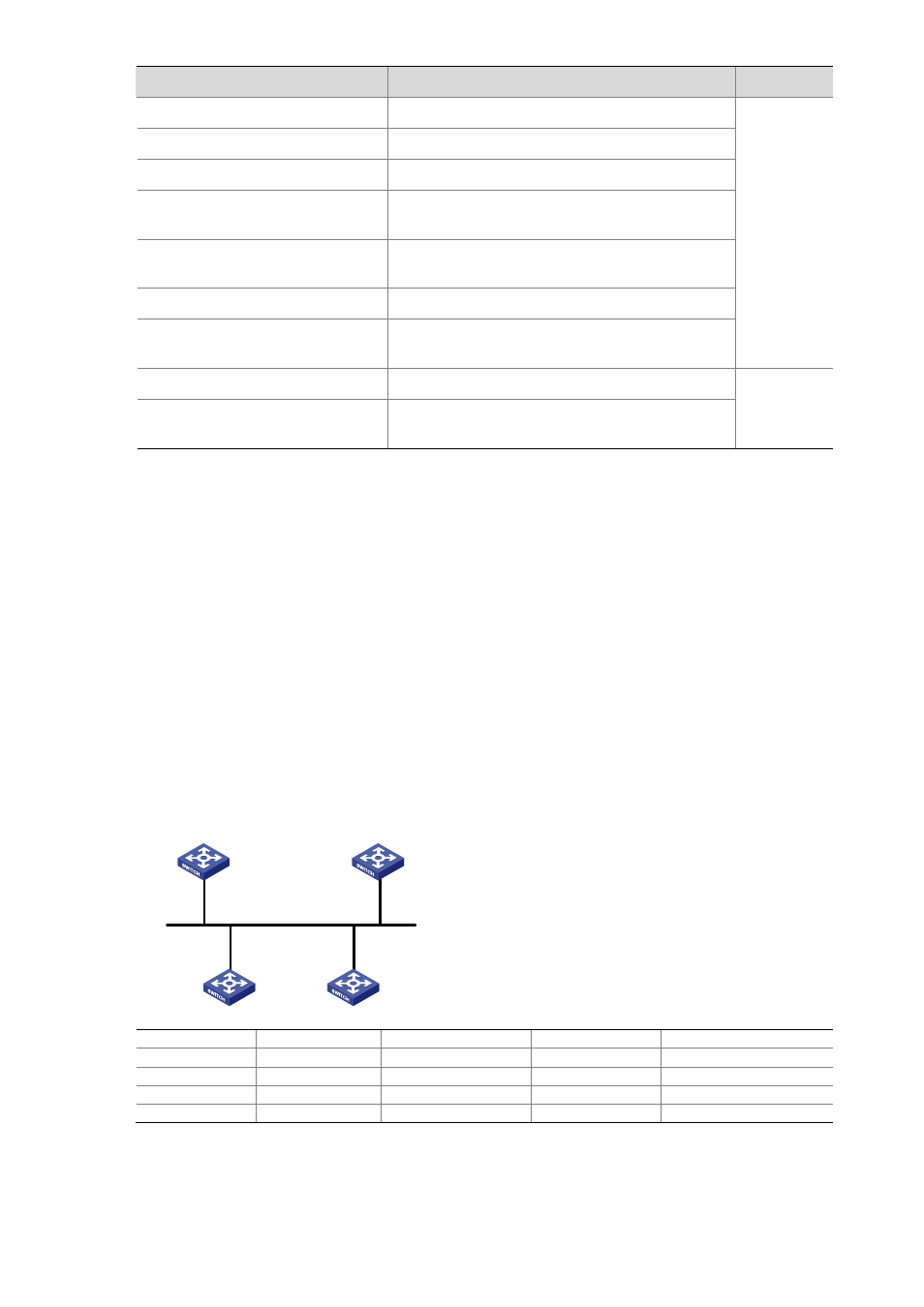
Figure 4-8 Network diagram for DR/BDR election
DR
BDR
Switch A
Switch D
Switch C
Switch B
Vlan-int1
Vlan-int1
Vlan-int1
Vlan-int1
Device
Interface
IP address
Router ID
Interface priority
Switch A
Vlan-int1
196.1.1.1/24
1.1.1.1
100
Switch B
Vlan-int1
196.1.1.2/24
2.2.2.2
0
Switch C
Vlan-int1
196.1.1.3/24
3.3.3.3
2
Switch D
Vlan-int1
196.1.1.4/24
4.4.4.4
1
Configuration procedure
# Configure Switch A.
