Ip performance configuration example, Network requirements, Network diagram – H3C Technologies H3C S3600 Series Switches User Manual
Page 133: Configuration procedure

2-5
To do…
Use the command…
Remarks
Clear IP traffic statistics
reset ip statistics
Clear TCP traffic statistics
reset tcp statistics
Clear UDP traffic statistics
reset udp statistics
Available in user view
IP Performance Configuration Example
Enabling the Reception of Directed Broadcasts to a Directly Connected Network
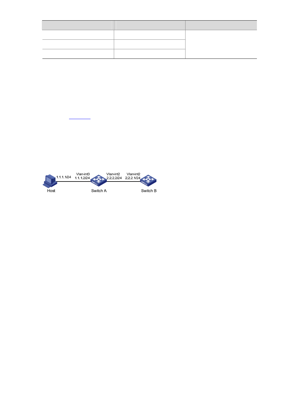
Network requirements
As shown in
, the host’s interface and VLAN-interface 3 of Switch A are on the same network
segment (1.1.1.0/24). VLAN-interface 2 of Switch A and VLAN-interface 2 of Switch B are on another
network segment (2.2.2.0/24). The default gateway of the host is VLAN-interface 3 (IP address
1.1.1.2/24) of Switch A. Configure a static route on Switch B to the host.
Network diagram
Figure 2-1 Network diagram for enabling the reception of directed broadcast
Configuration procedure
1) Configure Switch A
# Enable Switch A to receive directed broadcasts.
[SwitchA] ip forward-broadcast
# Configure IP addresses for VLAN-interface 3 and VLAN-interface 2.
[SwitchA] interface vlan-interface 3
[SwitchA-Vlan-interface3] ip address 1.1.1.2 24
[SwitchA-Vlan-interface3] quit
[SwitchA] interface vlan-interface 2
[SwitchA-Vlan-interface2] ip address 2.2.2.2 24
2) Configure Switch B
# Enable Switch B to receive directed broadcasts.
[SwitchB] ip forward-broadcast
# Configure a static route to Host.
[SwitchB] ip route-static 1.1.1.1 24 2.2.2.2
# Configure an IP address for VLAN-interface 2.
[SwitchB] interface vlan-interface 2
