Hide, isolate, and change the appearance of parts – Adobe Acrobat 9 PRO Extended User Manual
Page 398
392
USING ACROBAT 9 PRO EXTENDED
3D models and geospatial PDFs
Last updated 9/30/2011
The author of the PDF can set up a 3D model in the conversion settings so that clicking it automatically displays the
Model Tree.
Hide, isolate, and change the appearance of parts
Some 3D models are composed of individual parts. You can use the Model Tree to hide or isolate parts, zoom in to
parts, or make parts transparent. Parts that show in the 3D model appear in the tree with a check mark next to them.
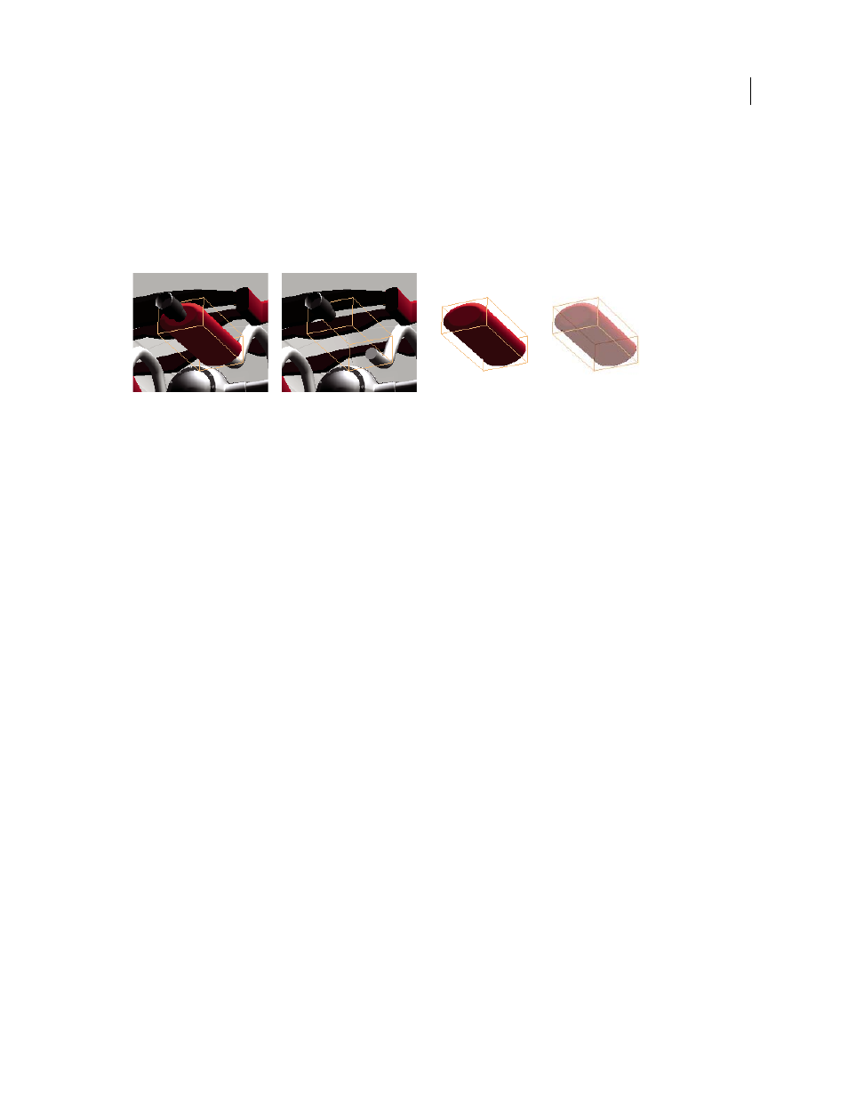
Manipulating parts
A. Selected part B. Hidden part C. Isolated part D. Transparent part
1 In the 3D model, use the Hand tool to click the part you want to manipulate. If a preference setting prevents you
from using the Hand tool, select the part in the Model Tree list.
2 From the Options menu in the top pane of the Model Tree, choose any of the following:
Note: The items that appear on the Options menu depend on whether the 3D model is composed of just one part or
multiple parts. Many of these options are also available by right-clicking a part in the 3D model.
Model Render Mode
Changes the surface appearance of the entire 3D model according to the item you choose from
the submenu: Transparent Bounding Box, Solid, Transparent, Solid Wireframe, and so on.
Show All Parts
Displays the entire 3D model.
Fit Visible
Displays all visible parts and centers them in the view.
Show Physical Properties
Displays the surface area and volume (if available) in the Object Data pane of the Model Tree.
Display Bounding Box
Displays the box that encloses the 3D object or selected parts of the model.
Set Bounding Box Color
Changes the color of the bounding box. Choose this option, select a color, and then click OK.
Hide
Displays the model without showing the selected parts. You can also select and deselect check boxes in the top
pane of the Model Tree to hide and show different parts.
Isolate
Displays only the selected part, hiding all others.
Isolate Part
Displays the geometry, the Product Manufacturing Information (PMI), and all views (including PMI
views) for the isolated part only. Views and information for all other parts are hidden or deselected. Changes occur in
the Model Tree as well. In the Structure pane (top), only the isolated part is selected. The structure of the other parts
is available but deselected. The View pane (middle) lists only the views that have been defined for the isolated part,
including PMI views. If you click a view, you see only the PMI for that view in the document pane. (To view the PMI
for the isolated part, make sure 3D PMI is selected in the Structure pane.) The View pane hides views related to the
assembly or other parts, including custom views created in Acrobat. You can add parts to the view by selecting them
in the Model Tree. You can also use the Hide/Show commands in the options menu of the Model Tree. To cancel the
isolated part, do any of the following:
•
Select another part with the Isolate Part command.
•
Select the top assembly in the Model Tree.
A
B
C
D