FUJITSU MB91460 SERIES FR60 User Manual
Page 955
939
Chapter 47 LCD Controller
7.Q&A
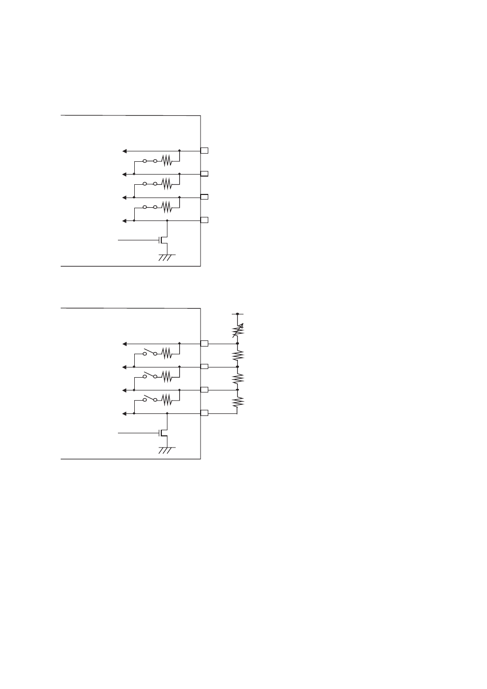
7.9 How do I select internal or external divided resistors?
• When using internal divided resistors:
• When using external divided resistors:
The LCD driving voltage can be generated by connecting external divided resistors to the LCD drive power
supply pins (V0 to V3).
To avoid the effect of internal divided resistors, the resistors must be disconnected by setting “0” to the LCD
drive power supply control bit (LCR0.VSEL).
7.10 How do I use external divided resistors to shut off the current when LCD is
deactivated?
The V0 pin is internally connected to Vss (GND) via a transistor. For this reason, the current generated on
deactivating LCD controller can be shut off by connecting external divided resistors to the V0 pin on the Vss
side. To shut off the current, use the display mode select bit (MS[1:0]= “00”).
V3
V2
V1
V0
N-ch
R
R
R
V
3
V
2
V
1
V
0
LCDC operation
enabled
VR
RX
RX
RX
V3
V2
V1
V0
N-ch
R
R
R
V
3
V
2
V
1
V
0
LCDC operation
enabled
- XG Series P3NK-4452-01ENZD (614 pages)
- FPCAC14C (1 page)
- MCJ3230SS (161 pages)
- MBA3073NC (138 pages)
- T5140 (102 pages)
- T5140 (76 pages)
- MAM3367MC/MP (152 pages)
- MPC3045AH (185 pages)
- MB2142-02 (23 pages)
- MB15F86UL (6 pages)
- MHS2030AT (40 pages)
- MHW2100BS (296 pages)
- MHK2060AT (227 pages)
- Disk Drives MHK2060AT (227 pages)
- MCM3064SS (170 pages)
- Mainboard D1561 (45 pages)
- MHC2040AT (219 pages)
- D1961 (45 pages)
- DISK DRIVES MHM2100AT (231 pages)
- MHR2010AT (250 pages)
- MHZ2120BJ (320 pages)
- MCE3064AP (175 pages)
- LQFP-64P (16 pages)
- Solaris PCI GigabitEthernet 3.0 (115 pages)
- MAY2036RC (94 pages)
- MAB3091 (142 pages)
- MPE3XXXAT (191 pages)
- MHV2040AH (40 pages)
- MHW2040AC (278 pages)
- ETERNUSmgr P2X0-0202-01EN (64 pages)
- VSS Hardware Provider 2.1 (134 pages)
- MAG3182FC (61 pages)
- MAU3147NC/NP (130 pages)
- MAX3147RC (94 pages)
- MHV2160BT (296 pages)
- MHV2040AT (280 pages)
- MAW3300NC/NP (130 pages)
- DeskPower E623 (50 pages)
- MAG3182LC (133 pages)
- OPTICAL DISK DRIVES MDG3064UB (42 pages)
- MHF2021AT (225 pages)
- MHR2040AT (40 pages)
- Single Drive FTM7926FB (1 page)
- PG-FCS103 (98 pages)
- MAS3735FC (114 pages)