Burst access operation – FUJITSU MB91460 SERIES FR60 User Manual
Page 590
574
Chapter 31 External Bus
6.Burst Access Operation
6. Burst Access Operation
In the external bus interface, the operation that transfers successive data items in one access
sequence is called burst access. The normal access cycle (that is, not burst access) is called
single access. One access sequence starts with an assertion of AS and CSn and ends with ne-
gation of CSn. Multiple data items two or more units of data of the unit set for the area.
This section explains burst access operation.
■
Burst Access Operation
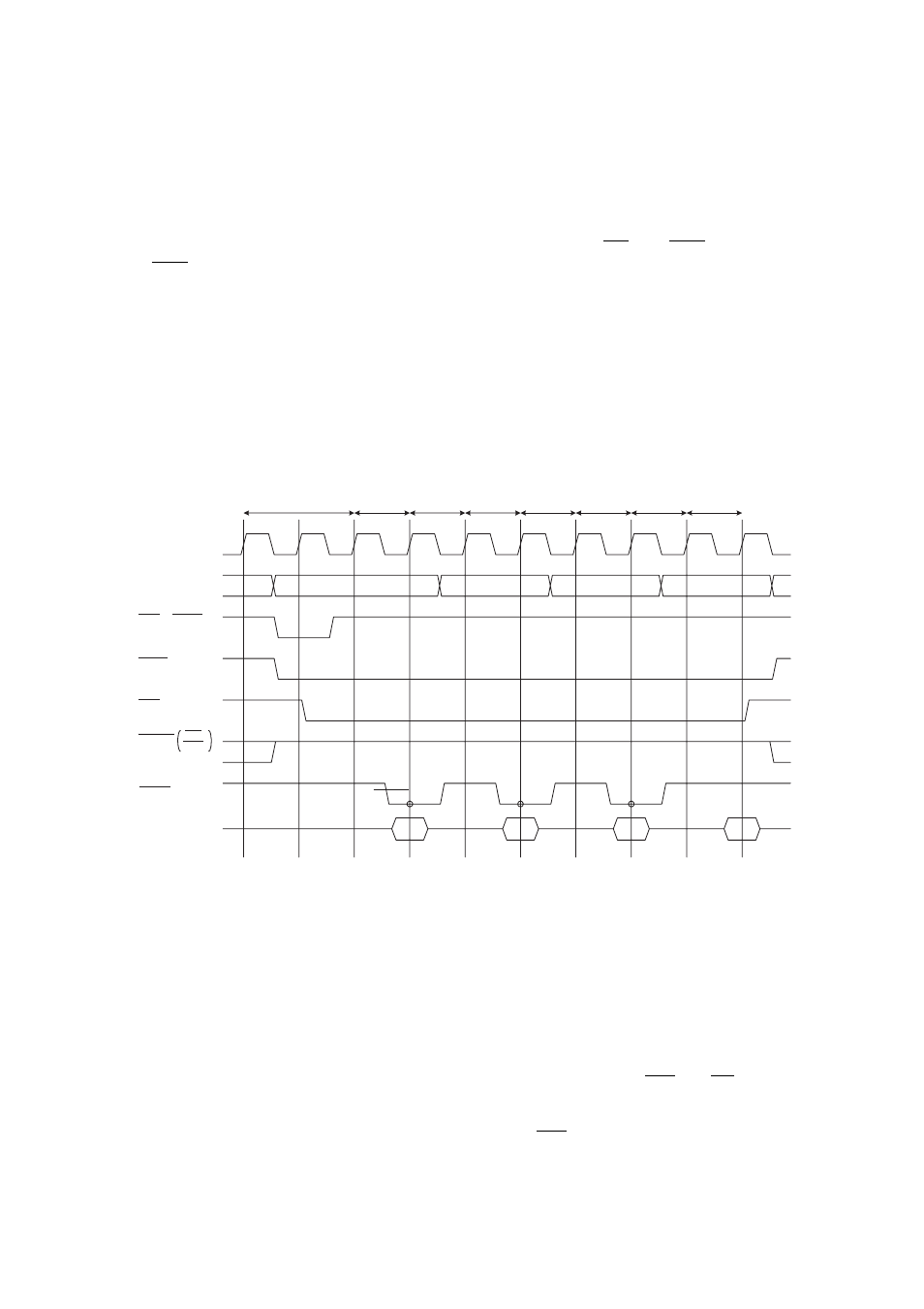
"Timing chart for burst access" shows the operation timing chart for (first wait cycle=1, inpage access
wait cycle=1, TYP3-0=0000
B
, AWR=1108
H
).
Figure 6-1 Timing Chart for Burst Access
•
In addition to more efficient use of access cycles when a sizable amount of data of asynchronous memory
such as page mode ROM and burst flash memory is read, burst cycles can also be used for reading from
normal asynchronous memory.
•
The access sequence when burst cycles are used can be divided into the following two types:
- First access cycle
The first access cycle is the start cycle for the burst access and operates in the same way as the normal single
access cycle.
- Page access cycle
The page access cycle is a cycle following the first access cycle in which both CSn and RD (read strobe) are
asserted. Wait cycles that are different from those set for a single cycle can be set. The page access cycle is
repeated while access remains in the address boundary determined by the burst length setting. When access
within the address boundary ends, burst access terminates and CSn is negated.
•
Setting of the W15-W12 bits of the AWR register enable the first 0-15 wait cycles to be inserted. At this point,
MCLK
AS
CSn
RD
WRn
D[31:0]
A[31:0]
BAA
First
cycle
wait
Inpage
access
wait
Inpage
access
wait
Inpage
access
wait
(LBA)
WRn
WR