Operation, 1 init pin input – FUJITSU MB91460 SERIES FR60 User Manual
Page 269
253
Chapter 18 Timebase Counter
5.Operation
5. Operation
This section describes the events that trigger an oscillation stabilization wait and the operation in each case.
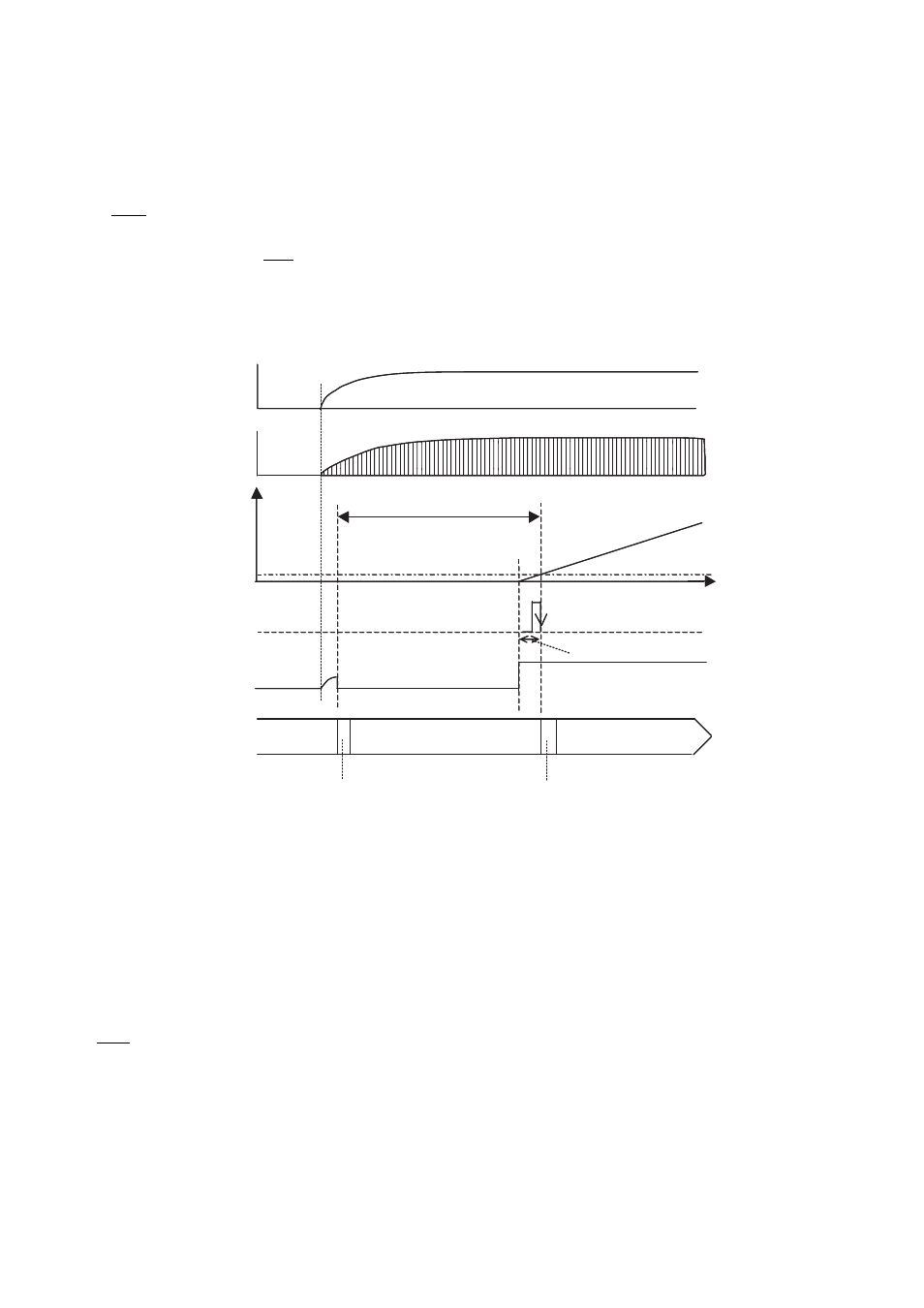
5.1 INIT Pin Input
An oscillation stabilization wait is required after power on. As the wait time provided by the initialized timebase
counter is too short, the INIT pin input must be held at the “L” level.
Figure 5-1 Using the Width of the Pin Input to Provide the Oscillation Stabilization Wait Time
(1) Power turned on
(2) Start INIT pin input (Settings initialization reset)
(3) Main clock oscillation starting
(4) INIT pin input (to provide a sufficient time for the main clock oscillation to stabilize)
(5) INIT pin input removed. The timebase counter is initialized and starts counting.
(6) Oscillation stabilization wait time provided by timebase timer/counter (Initial value = minimum value)
(If the INITX pin input (4) is not maintained, the wait time is too short.)
(7) Operation initialization reset, reset cancellation sequence
(8) Main RUN
■
INIT Pin input when main clock running
The device goes to the operation initialization reset (RST) state automatically after the minimum oscillation
stabilization wait time elapses.
(6)
(4)
(7)
(3)
INIT pin input
Time-base
counter count
Time
000h
Example main clock startup
(2)
2 (Bit 0 output)
1
Provide a sufficient oscillation
stabilization wait time
(5)
Settings initialization
(INIT)
Operation initialization (SRST)
Reset cancellation sequence
Oscillation stabilization wait reset
Undefined
State transition
Main RUN
Using the INIT pin input to trigger
a reset and provide the oscillation
stabilization wait time for the
main clock
2
1
(1)
Example power-on Vcc
(2)
(8)
(5)
Initial value of oscillation
stabilization wait time is too short