FUJITSU MB91460 SERIES FR60 User Manual
Page 332
316
Chapter 24 Interrupt Control
4.Registers
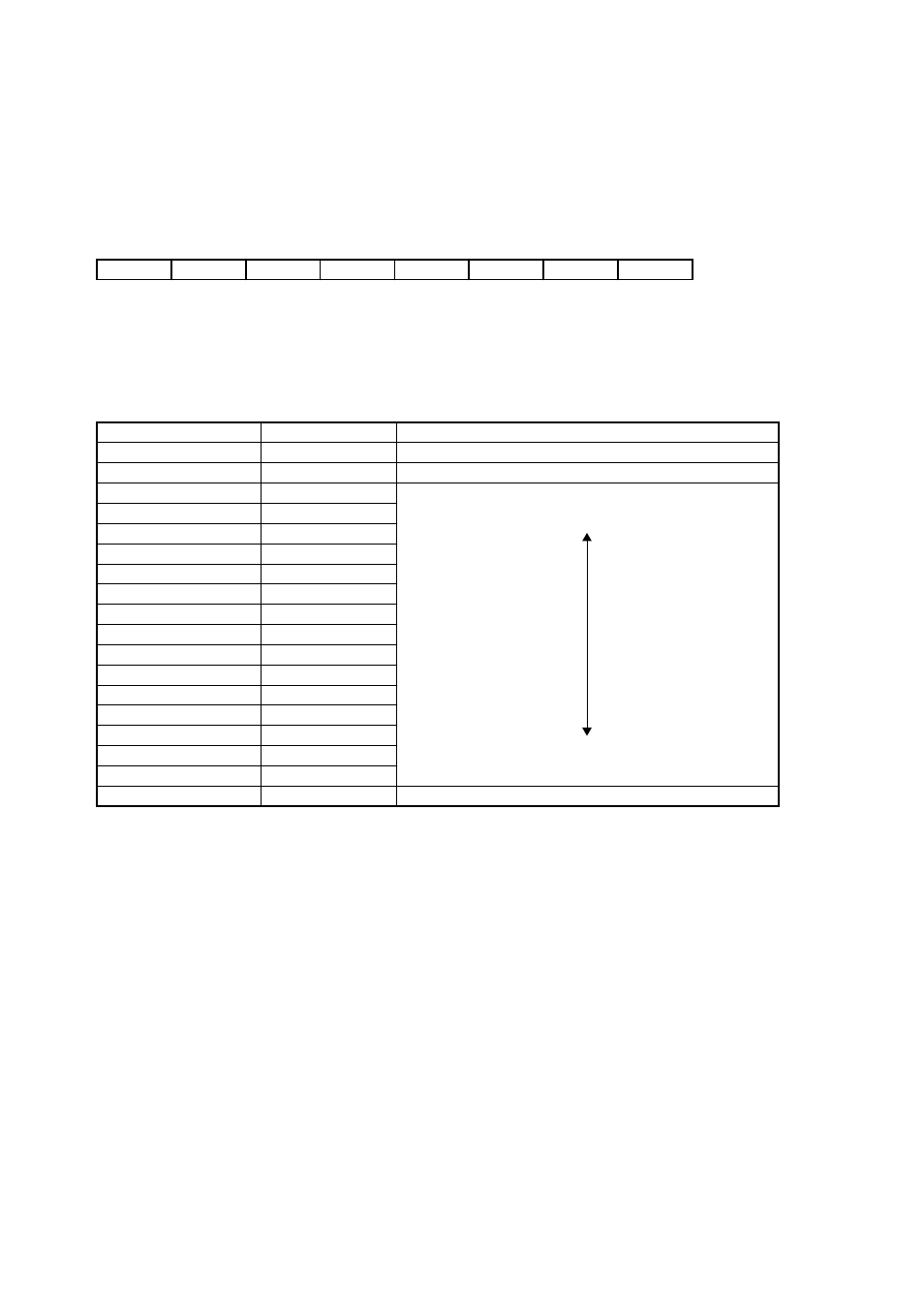
ICR (Interrupt Control Register) is a register in the interrupt controller, and it specifies the interrupt level for
each interrupt request. ICR corresponds to each of interrupt request input. ICR is mapped to the I/O space.
• ICR00 – ICR63
(About attributes, see “
Meaning of Bit Attribute Symbols (Page No.10)
”.)
• Bit 7-5: Undefined. Writing does not affect the operation. The read value is indeterminate.
• Bit 4-0: Interrupt level setting bits
• The interrupt level setting bit specifies the interrupt level of the corresponding interrupt request.
• When the interrupt level set to the interrupt control register is the same as, or higher than the level mask
value set to the ILM register of the CPU, the interrupt request is masked by the CPU side.
7
6
5
4
3
2
1
0
bit
–
–
–
ICR4
ICR3
ICR2
ICR1
ICR0
–
–
–
1
1
1
1
1
Initial
value
RX/WX
RX/WX
RX/WX
R/WX
R/W
R/W
R/W
R/W
Attribute
ICR4-ICR0 bits
Interrupt level
Description
0000-01110
0-14
Reserved for system (cannot to be set)
01111
15
NMI
10000
16
The highest level
10001
17
(High)
10010
18
10011
19
10100
20
10101
21
10110
22
10111
23
11000
24
11001
25
11010
26
11011
27
11100
28
11101
29
(Low)
11110
30
The lowest level
11111
31
Disable interrupts