FUJITSU MB91460 SERIES FR60 User Manual
Page 857
841
Chapter 41 Up/Down Counter
4.Register
F
CLKP
: Frequency of Peripheral clock (CLKP)
This setting is enabled only in the timer mode, in which only countdown is performed.
• bit11,10: Select count mode
• bit9,8: Select count clock edge
This bit is used in the up/down count mode (CMS1,CMS0= “01”) to select the edge, to be detected, of an
AIN and BIN pin signal. This setting is disabled in modes other than the up/down count.
• bit7: Reserved.
Be sure to write “0”. The read value is the value written.
• bit6: Counter write
During count operation (CSR.CSTR=“1”), the counter write bit must not be set to “1”.
• bit5: Enable compare-match clear
This setting does not affect clear operations other than compare-match, such as ZIN pin clear.
• bit4: Enable reload
If the reload enable bit is set to “1”, the reload/compare value (RCR) is transferred to Up/Down Counter
(UDCR) when Up/Down Counter is underflowed.
• bit3: Clear UDCR
• bit2: Select counter clear/gate
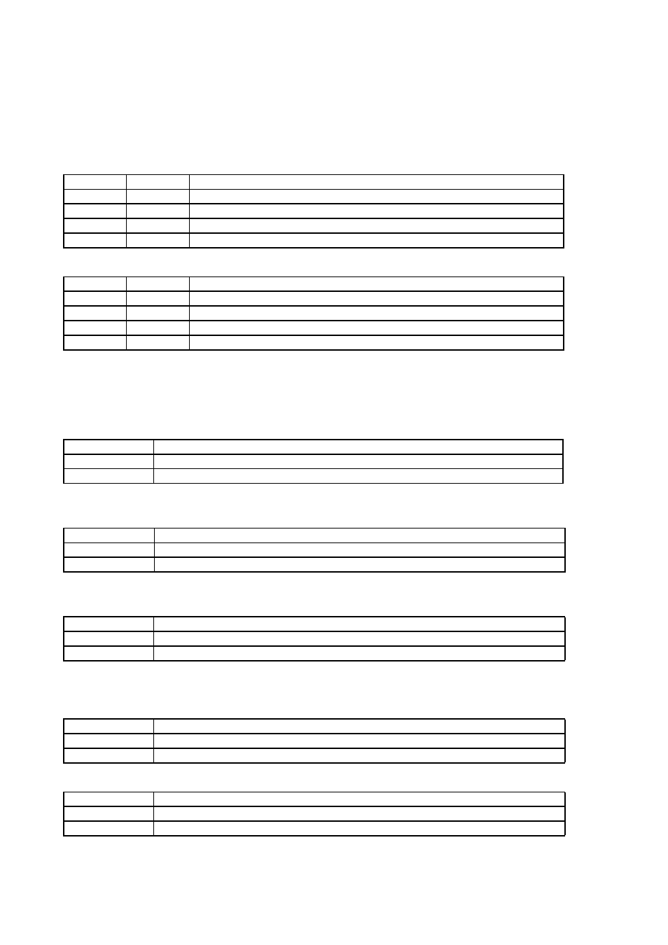
CMS1
CMS0
Count mode
0
0
Timer mode (Countdown)
0
1
Up/down count mode
1
0
Phase difference count mode (Multiply by 2)
1
1
Phase difference count mode (Multiply by 4)
CES1
CES0
Edge selection
0
0
Disable edge detection.
0
1
Detect a falling edge.
1
0
Detect a rising edge.
1
1
Detect both rising and falling edges.
CTUT
Data transfer
0
No impact on operation
1
Transfer data from the RCR register to UDCR.
UCRE
Compare-match counter clear
0
Disable counter clear due to compare-match.
1
Enable counter clear due to compare-match.
RLDE
Reload function
0
Disable reload function.
1
Enable reload function.
UDCLR
Counter clear
0
Set (Clear) Up/Down Counter (UDCR) to “0000H”.
1
No impact on operation
CGSC
ZIN pin function
0
Counter clear function
1
Gate function