Fly-by transfer mode, Figure 6-3 – FUJITSU MB91460 SERIES FR60 User Manual
Page 397
381
Chapter 26 DMA Controller
6.DMA External Interface
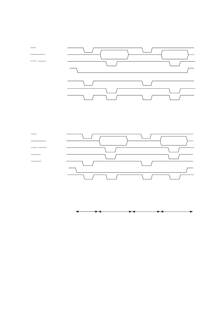
Figure 6-3 Timing Chart in 2-Cycle Transfer Mode
●
Fly-by transfer mode
"Timing Chart in Fly-By Transfer Mode" shows the timing chart in fly-by transfer mode.
Figure 6-4 Timing Chart in Fly-By Transfer Mode
RD
DQMU/L
WR/WRn
DACK (AKxx=111
B
)
*
Same timing as the chip select
DACK (AKxx=001
B
)
*
2-cycle transfer setting disabled
DACK (AKxx=100
B
)
*
DACK (AKxx=101
B
)
*
* : AKxx is the setting value in the PFR register that corresponds to the DMA channel.
DACK (AKxx=010
B
)
*
DACK (AKxx=011
B
)
*
DACK (AKxx=110
B
)
*
RD
DQMU/L
WR/WRn
IORD
IOWR
DACK (AKxx=111
B
)
*
Same timing as the chip select
DACK (AKxx=001
B
)
*
DACK (AKxx=010
B
)
*
Fly-by transfer setting disabled
DACK (AKxx=011
B
)
*
Fly-by transfer setting disabled
DACK (AKxx=100
B
)
*
Fly-by transfer setting disabled
Memory to I/O I/O to memory
Memory to I/O
I/O to memory
* : AKxx is the setting value in the PFR register that corresponds to the DMA channel.
DACK (AKxx=101
B
)
*
Fly-by transfer setting disabled
DACK (AKxx=110
B
)
*
Fly-by transfer setting disabled