P0tmr, p1tmr structure – FUJITSU MB91460 SERIES FR60 User Manual
Page 844
828
Chapter 40 Pulse Frequency Modulator
2.Reload Counter Registers
Writing "1" sets the counter to wait for a trigger.
Writing "0" stops count operation.
[Bit 0] TRG
Software trigger bit.
Writing "1" to TRG applies a software trigger, causing the counter to load the reload register
contents to the counter and start counting.
Writing "0" has no meaning. Reading always returns "0".
Applying a trigger using this register is only valid when CNTE = "1". Writing "1" has no effect if
CNTE = "0".
■
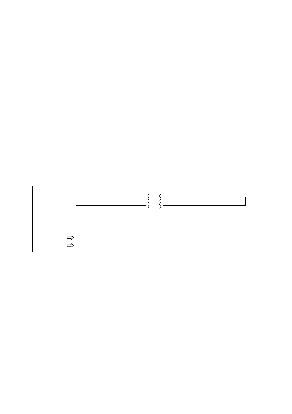
16-bit Counter Register (P0TMR, P1TMR)
Reading this register reads the count value of the 16-bit counter.
The initial value is indeterminate.
Always read this register using 16-bit data transfer instructions.
●
P0TMR, P1TMR structure
Figure 2-2 Structure of the 16-bit Counter Register
■
16-bit Reload Register (P0TMRLR, P1TMRLR)
The 16-bit reload register stores the initial count value.
The initial value is indeterminate.
Always write to this register using 16-bit data transfer instructions.
Access
0
R
Address
15
×
Initial value
0000 0174
H
R
×
R
×
R
×
• • •
• • •
R
×
R
×
R
×
R
×
R
×
0000 0178
H