5 sample use of hardware sequence flag – FUJITSU MB91460 SERIES FR60 User Manual
Page 1022
1006
Chapter 54 Flash Memory
7.Auto Algorithms
7.5 Sample Use of Hardware Sequence Flag
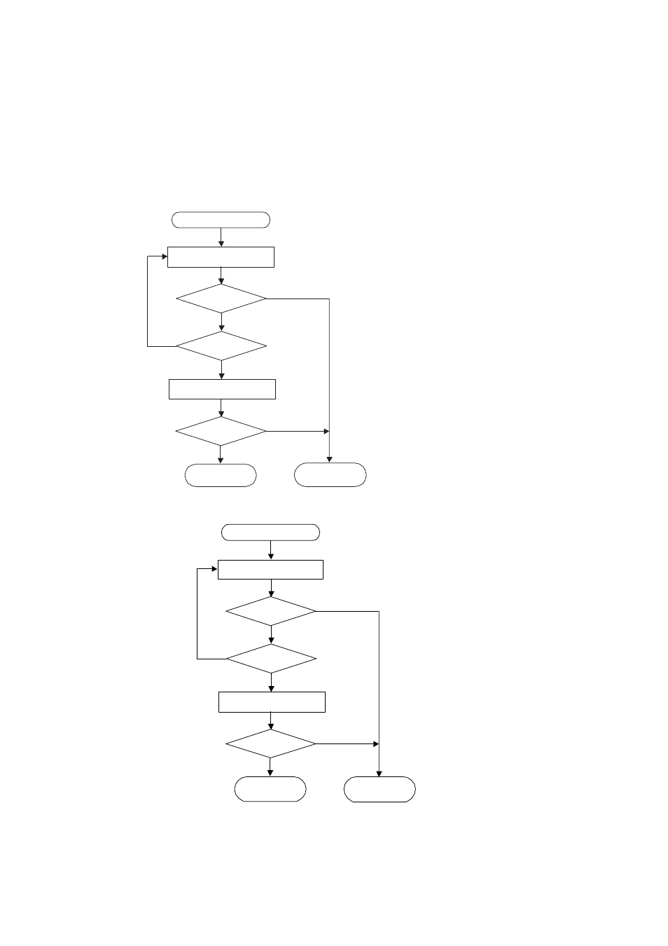
It is possible to determine the state of the Flash memory’s internal Auto Algorithms using the hardware
sequence flag mentioned above. As an example, the figures below show the write/erase determination
sequence when the data-polling function is used, and when the toggle-bit function is used.
Figure 7-4 Write/erase Determination Sequence Using Data-polling Function
Figure 7-5 Write/erase Determination Sequence Using Toggle-bit Function
VA = write address
= Erased sector address during
sector erase
= Non-protected sector address
during chip erase
* : Since D7 changes at the same time
as D5, even if D5 = "1", D7 must
be rechecked.
Start write/erase
Read (D0 to D7)
address = VA
Read (D0 to D7)
address = VA
D7 = Data?
Write/erase Fail
D5 = 1?
D7 = Data?
*
Write/erase Pass
YES
YES
YES
NO
NO
NO
* When D5 changes to "1", D6 stops toggling, so even if
D5 = "1", D6 must be rechecked.
Start write/erase
Read (D0 to D7)
address = "H" or "L"
Read (D0 to D7)
address = "H" or "L"
D6 = Toggle?
Write/erase Fail
D5=1 ?
D6 = Toggle?
*
Write/erase Pass
NO
NO
NO
YES
YES
YES