Configuration, Standby control – FUJITSU MB91460 SERIES FR60 User Manual
Page 172
156
Chapter 10 Standby
3.Configuration
3. Configuration
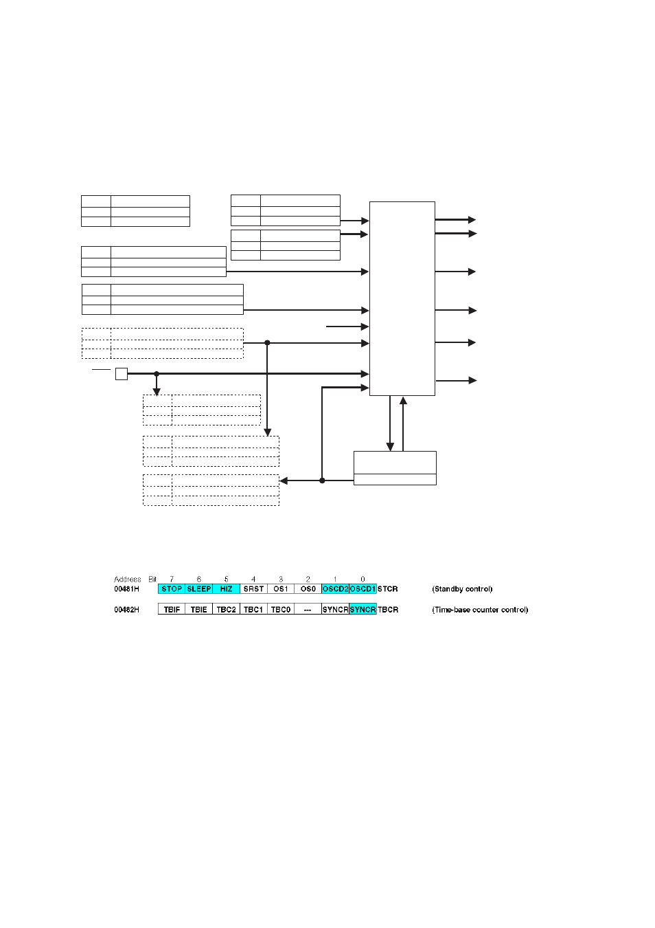
Figure 3-1 Configuration Diagram
Figure 3-2 Register List
State
transition
control
circuit
Sleep signal
WDOG
0
1
RSRR: bit5
No watchdog timeout
Watchdog timeout (INIT) occurred
SRST
0
1
RSRR: bit3
No software reset (RST)
Software reset (RST) occurred
INIT
0
1
RSRR: bit7
No INIT pin input
INIT pin input occurred (INIT)
Oscillation stabilization
wait finished
Counter cleared,
oscillation
stabilization
wait
Time-base counter
(oscillation stabilization wait)
Watchdog timer
SRST
0
1
STCR: bit4
Generate software reset.
Do not generate software reset.
INIT
Stop signal
Clock control
Pin control
Initialize settings (INIT)
Initialize operation (RST)
Internal interrupts,
external interrupts
STOP
0
1
STCR: bit7
Do not change to stop mode.
Change to stop mode.
SLEEP
0
1
STCR: bit7
Do not change to sleep mode.
Change to sleep mode.
OSCD1
0
1
STCR: bit0
Do not halt main clock oscillation during stop mode.
Halt main clock oscillation during stop mode.
HIZ
0
1
STCR: bit5
Maintain same states during stop mode.
Set pins to high impedance during stop mode.
SYNCS
0
1
TB CR: bit0
Setting prohibited
Synchronous standby
State transition control circuit
(for standby modes)
Standby control