Q & a, 1 where should i set digital values, 2 how do i program the d/a pins for d/a output – FUJITSU MB91460 SERIES FR60 User Manual
Page 931: 3 how do i enable or disable d/a output, 4 how do i activate a d/a conversion, Q & a 7.1 where should i set digital values
915
Chapter 45 D/A Converter
7.Q & A
7. Q & A
7.1 Where should I set digital values?
Write digital values to the D/A Data Registers (DADR[7:0] for 8-bit mode, DADR[9:0] for 10-bit mode).
Access in a byte or halfword format.
D/A conversion begins immediately on writing.
7.2 How do I program the D/A pins for D/A output?
DA Pin output setting
Setting is accomplished by writing “1” to the output specification bits (PFR28.7 for DA1), (PFR28.6 for DA0).
(Switch the port to DA pin output by software programming.)
7.3 How do I enable or disable D/A output?
Use the D/A output control bits (DACR.DAE0), (DACR.DAE1).
O V (= AVss) is output when disabled. This is functional even while in a stopped state.
7.4 How do I activate a D/A conversion?
A conversion begins on writing a digital value. See 7.1.
7.5 What is the formula used to work out the value necessary to produce an expected
voltage?
Equation
Value = [{V (Expected analog value) x 1024} / (AV
CC
)]
To output 2.8 V from the pin with AV
CC
= 5.0V, for example.
(2.8V x 1024) / 5.0V = 573.44 => Value = 573
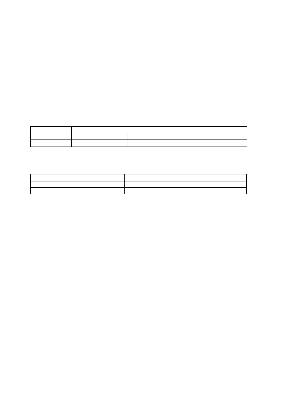
Pins
Control bit location
DA0 pin
PFR28.6 = ‘1’
DA0 Output specification bit (DA0)
DA1 pin
PFR28.7 = ‘1’
DA1 Output specification bit (DA1)
Operations
D/A output control
bit (DAE)
To disable output
Set “0”.
To enable output
Set “1”.