Figure 3-2 configuration diagram, Chapter 41 up/down counter 3.configuration, Up/down counter 1 (8 bit mode) – FUJITSU MB91460 SERIES FR60 User Manual
Page 853: Udcr1 udrc1, 8 bit mode, Peripheral clock clkp, Udc1 interrupt (#129)
837
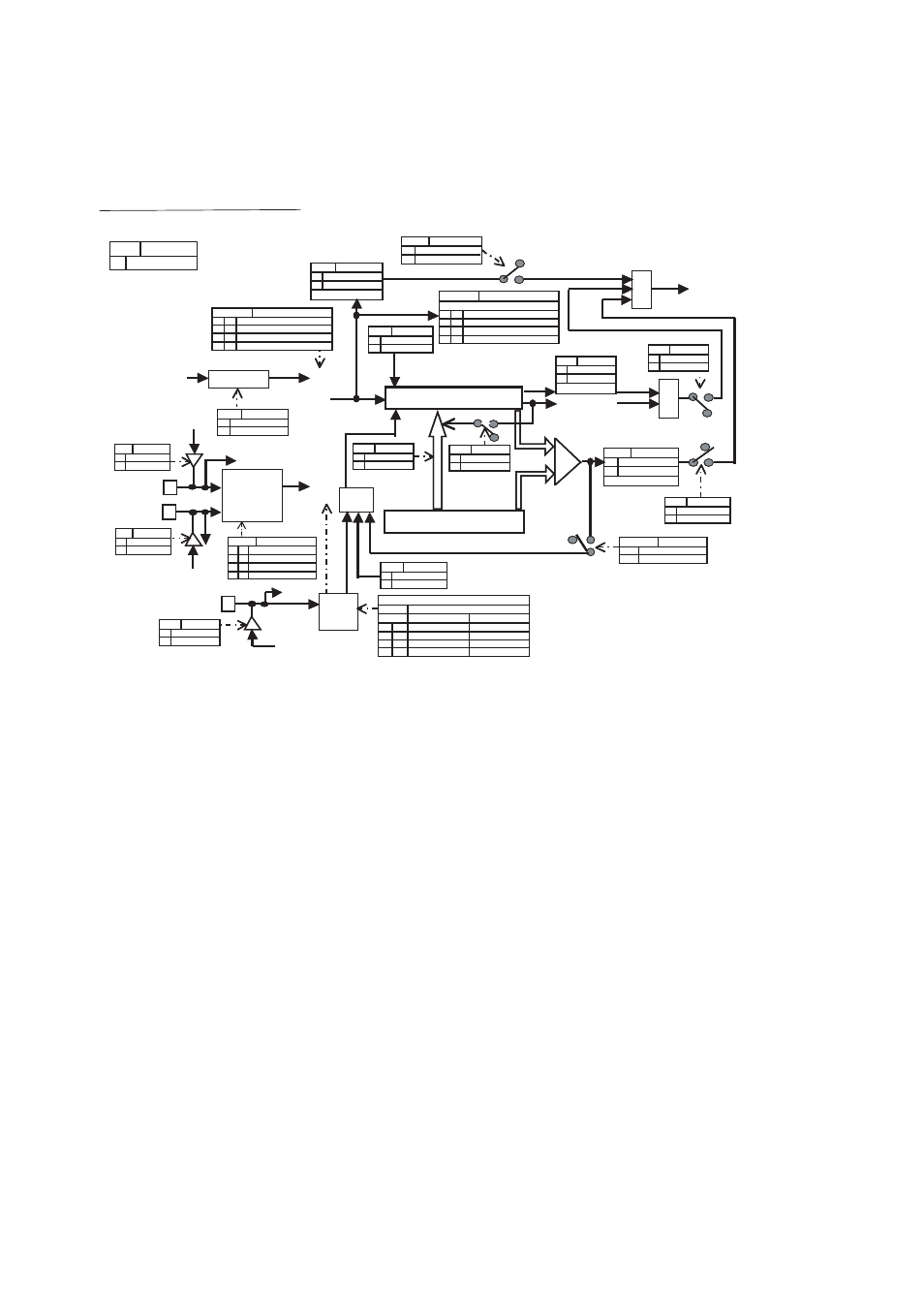
Chapter 41 Up/Down Counter
3.Configuration
Figure 3-2 Configuration Diagram
UDCR1
UDRC1
CITE
UDCS1: bit6
0
1
CMS1-0
UDCC1: bit11 -10
0
0
1
1
0
1
1
0
CES1-0 UDCC1: bit 9-8
0
0
1
1 0
1 1
0
UDCC1: bit1-0, bit 2
CGE1-0
0
0
1
1
0
1
1
0
CGSC
UDCLR UDCC1: bit2
0
1
Clear
Disabling
UDIE
UDCS1: bit5
1
0
UDFF
UDCS1: bit2
0
1
CSTR
UDCS1: bit7
0
1
Start counting
CFIE
UDCC1: bit 13
0
1
CLKS
UDCC1: bit 12
0
1
OR
OR
1
1
1
0
0
1
0
0
UDF1-0
UDCS1: bit 1-0
0
0
1
1
0
1
1
0
M16E UDCC0 : bit15
0
8 bit mode
Up/Down Counter 1 (8 Bit Mode)
AIN1/SIN3/P20.4
P20 EPFR20.4
0
1
BIN1/SOT3/P20.5
P20 EPFR20.5
0
1
ZIN1/SCK3/P20.6
P20 EPFR20.6
0
1
OR
UCRE
UDCC1:bit5
0
1
CTUT UDCC1: bit6
0
1
1
0
RLDE UDCC1: bit4
0
1
CDCF
UDCC1: bit14
0
1
CMPF
UDCS1: bit4
0
1
OVFF
UDCS1: bit3
0
1
-
-
0
0
1
1
0
1
1
0
0 0
0
0
0
0
1
-
-
0
0
0
0
0
0
0
Timer mode (Countdown only)
Up/down count mode
Phase difference count mode (Multiply by 2)
Phase difference count mode (Multiply by 4)
No change direction
Direction changed
Stop counting
Disable interrupts
Enable interrupts
8 bit mode
WRITE 0: Flag clear
Peripheral clock
CLKP
Prescaler
CLKP divided by 2
CLKP divided by 8
From port data
register
From port data
register
From port data
register
Others
Enable UDC
Others
Enable UDC
Others
Enable UDC
Read from port
Read
from
port
Read from
port
Edge
detection
Edge
detection
Disable edge detection
Enable falling edge detection
Enable rising edge detection
Enable both edge detection
Gate
Activation
No impact
Data transfer
* Only 16 bit transfer is enabled
while counting stops.
Up/Down Counter (Read only)
Reload/compare register (Write only)
Reload
Counter clear
Disable reload
Enable reload
No input
Countdown
Countup
Both countdown and countup
Write: Disabled, Read only
Selector/Count Control
Disable edge detection
Enable falling edge detection
Enable rising edge detection
Disable setting
Disable level detection
Enable LOW level detection
Enable HIGH level detection
Disable setting
1: Gate function
0: Counter clear function
Com-
pare
UDC1 interrupt
(#129)
Compare match
No compare match
Disable interrupts
Enable interrupts
Disable interrupts
Enable interrupts
No underflow
Underflowed
Disable counter clear
Enable counter clear
No overflow
Overflowed
WRITE 0: Flag clear
WRITE 0: Flag clear
WRITE 0: Flag clear