Configuration diagram, Chapter 35 free-run timer 3.configuration diagram – FUJITSU MB91460 SERIES FR60 User Manual
Page 750
734
Chapter 35 Free-Run Timer
3.Configuration Diagram
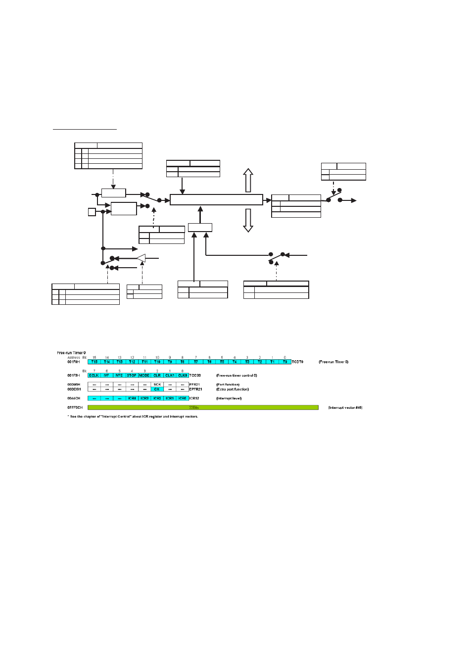
3. Configuration Diagram
Figure 3-1 Configuration Diagram
Figure 3-2 Register List
Note: See “
Chapter 24 Interrupt Control (Page No.311)
” about ICR register and interrupt vectors.
Free-run Timer
External clock
Divider
0
1
TCDT
OR
1
0
1
0
Count value
Free-run Timer
interrupt
Timer data register
Input capture
Output compare
Count value
Overflow flag
Peripheral clock
C LKP
CLK1-0
TCCS: bit 1-0
CLKP / 4
0
0
1
1
0
1
1
0
CLKP / 16
CLKP / 32
CLKP / 64
Count clock
IVFE
T CCS: bit 5
0
1
Disable interrupts
Enable interrupts
STOP
TCCS: bit 4
0
1
Count operation
Stop the count operation
ECLK
TCCS:bit 7
0
1
From the divider
From the outside
CLR
TCCS:bit 2
0
1
No effect
Clears the timer
CK /SCK/ Pxy.z
TCCS: bit 3
0
1
Disable the clear by the compare-match
Enable the clear by the compare-match
Notes: When using the input/output (SCK), the external clock (CK) cannot be used because the port is shared.
1
0
General-purpose port
SCK (USART shift clock)
From the port
data register
Clear
External clock
Synchronization
circuit
The clock selection
IVF
TCCS: bit 6
0
1
No interrupt requests
Interrupt request present
WRITE 0: Flag clear
(Resource
output)
Read of the port
GP
DDRxy.z
0
1
Input only
Enable output
CLKP / 4
0
0
1
1
0
1
1
0
CLKP / 16
CLKP / 32
CLKP / 64
0
0
1
1
0
1
1
0
0
0
1
1
0
1
1
0
MODE
0
1
0
The timer clear request by the
compare value match of the
output compare
CK (FRT clock input)
PFR/EPFR
Function
1
0
0
1
1
0
0
0
0
0
0
0