State transition diagram – FUJITSU MB91460 SERIES FR60 User Manual
Page 150
134
Chapter 8 Device State Transition
3.State Transition Diagram
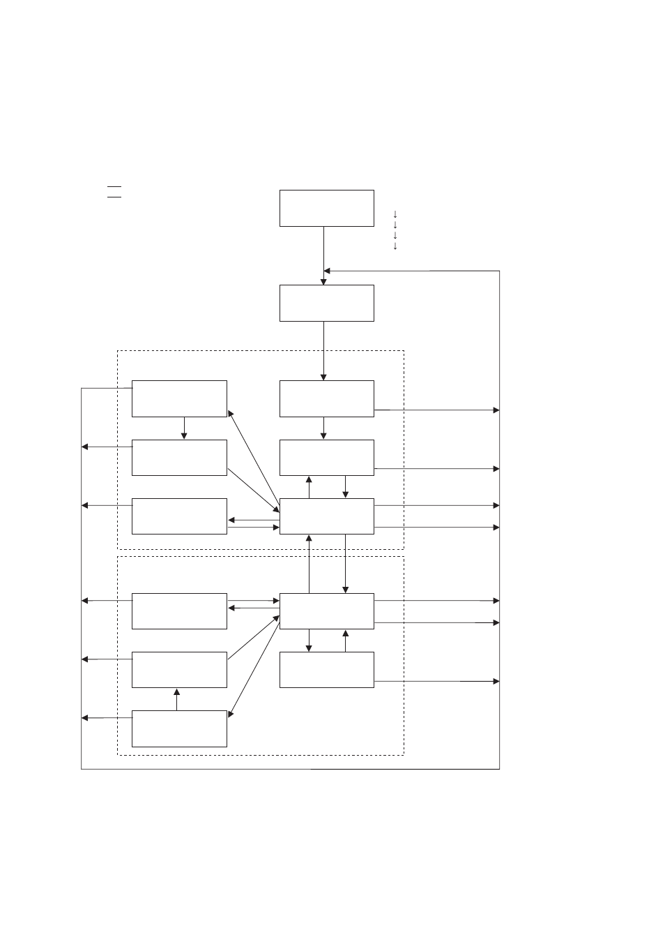
3. State Transition Diagram
This section describes state transition.
Figure 3-1 State Transition of MB91460 Series
Oscillation-
stabilization-
wait reset
Power-on
Setting initialization
(INIT)
Program reset
(RST)
Main RUN
Main sleep
Oscillation-
stabilization-wait RUN
Main stop
Sub-RUN
Sub-sleep
Oscillation-
stabilization-wait RUN
Program reset
(RST)
Sub-stop *
1
2
3
4
4
5
5
6
7
13
7
8
8
9
9
3
3
10
11
1
1
1
1
1
1
1
1
1
1
1
Main clock mode
Subclock mode
1
INIT pin = 0 (INIT)
2
INIT pin = 1 (Cancel of INIT)
3
Termination of oscillation-stabilization wait
4
Cancel of reset (RST)
5
Software reset (RST)
6
Sleep (Writing instruction)
7
Stop (Writing instruction)
8
Interrupt
9
External interrupt requiring no clock
10
Switching from main to sub (Writing instruction)
11
Switching from sub to main (Writing instruction)
12
Watchdog reset (INIT)
13
Sub-sleep (Writing instruction)
Priority of transition request
Highest
priority
Setting-initialization reset (INIT)
Termination of oscillation-stabilization wait
Operation-initialization reset (RST)
Interrupt request
Stop
Lowest
priority
Sleep
12
12
* To switch clock source between main and sub, in the RUN status where switched clock is stable,
switch clock source register (CLKR) between bit 1 and 0 (CLKS1 and CLKS0 bit).
MB91460 does not stop
oscillation while waiting
time is generated.