FUJITSU MB91460 SERIES FR60 User Manual
Page 898
882
Chapter 43 Stepper Motor Controller
3.Operation
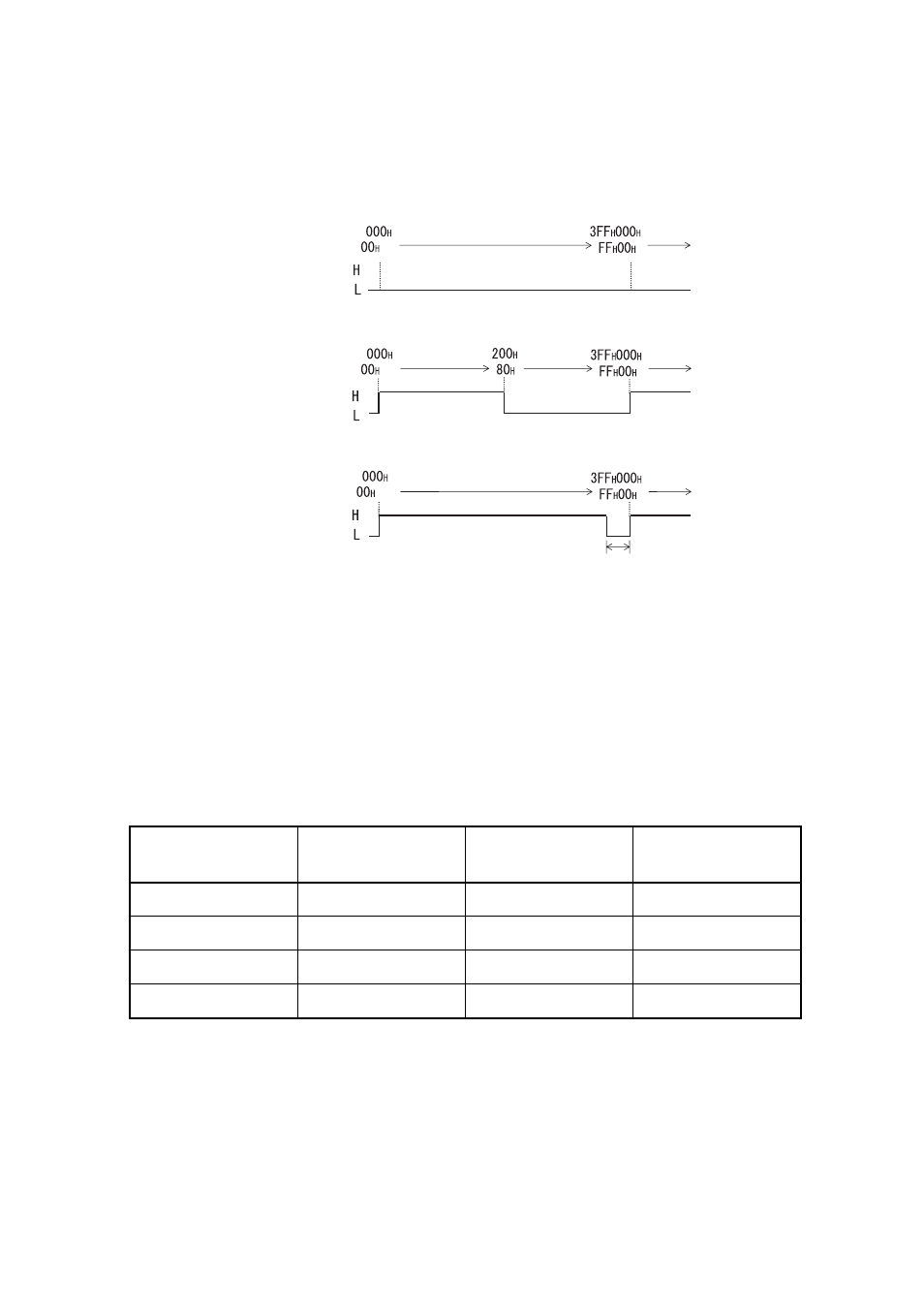
Figure 3-2 Examples of PWM1&2 Waveform Output
■
Selection of motor drive signals
Motor drive signals that are output to each pin related to the stepping motor controller can be selected among
four types of signals for each pin by setting the PWM selection register.
"Selection of Motor Drive Signals and Setting of PWM Selection Registers 1&2" lists the selection of the
motor drive signals and the settings of PWM selection registers 1&2.
When these registers are set and "1" is written to the BS bit of the PWM selection register 2, the setting of these
registers is enabled at the end of the current PWM cycle. The BS bit is to be cleared automatically to 0 at the
beginning of the next PWM cycle. When "1" is written to the BS bit, and the BS bit is cleared to 0 simultaneously
at the beginning of the next PWM cycle, "1" is written to the BS bit and clearing of the BS bit is cancelled.
Table 3-1 Selection of Motor Drive Signals and Setting of PWM Selection Registers 1&2
P2, P1, P0 Bits
PWM2P Output
PWM1P Output
M2, M1, M0 Bits
PWM1M Output
PWM2M Output
000
B
L
000
B
L
001
B
H
001
B
H
01X
B
PWM Pulse
01X
B
PWM Pulse
1XX
B
High impedance
1XX
B
High impedance
When the value of compare register is "00
H
"/"000
H
"(duty ratio is 0%):
When the value of compare register is "80
H
"/"200
H
"(duty ratio is 50%):
When the value of compare register is "FF
H
"/"3FF
H
"(duty ratio is 99.6%/99.9%):
Value of counter:
PWM waveform:
Value of counter:
PWM waveform:
Value of counter:
PWM waveform:
One count