FUJITSU MB91460 SERIES FR60 User Manual
Page 843
827
Chapter 40 Pulse Frequency Modulator
2.Reload Counter Registers
[Bits 9] Reserved
Always set to "0".
[Bits 8] MOD1
Sets the Trigger level to Falling edge (MOD1=’1’ is necessary for PFM operation)
[Bits 7 to 5] Reserved
Always set to "010".
[Bit 4] RELD
This bit enables reload operations.
When RELD is "1", the counter operates in reload mode. In this mode, the counter loads the
reload register contents into the counter and continues counting whenever an underflow
occurs (when the counter value changes from 0000
H
to FFFF
H
).
When RELD is "0", the count operation stops when an underflow occurs due to the counter
value changing from 0000
H
to FFFF
H
.
[Bit 3] INTE
The interrupt request enable bit.
When INTE is "1", an interrupt request is generated when the UF bit changes to "1".
When INTE is "0", no interrupt requests are generated.
[Bit 2] UF
The counter interrupt request flag.
UF is set to "1" when an underflow occurs (when the counter value changes from 0000
H
to
FFFF
H
).
Writing "0" clears the bit. Writing "1" has no meaning. Read as "1" by read-modify-write
instructions.
[Bit 1] CNTE
The counter count enable bit.
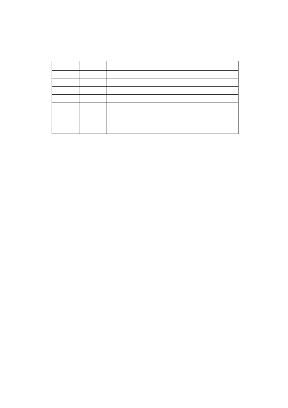
Table 2-1 CSL Bit Clock Source Settings
CSL2
CSL1
CSL0
Clock source (
φ
: Machine clock)
0
0
0
φ
/ 2
1
0
0
1
φ
/ 2
3
0
1
0
φ
/ 2
5
0
1
1
Setting disabled
1
0
0
Setting disabled
1
0
1
φ
/ 2
6
1
1
0
φ
/ 2
7
1
1
1
Setting disabled