FUJITSU MB91460 SERIES FR60 User Manual
Page 616
600
Chapter 31 External Bus
10.DMA Access Operation
•
For the I/O device on the receiving side, a write strobe of two bus cycles extended by the I/O wait cycle is
generated.
•
The I/O hold wait cycle does not affect the write strobe.
•
Fly - by transfer must always be performed between data buses having the same bus width.
•
When the I/O wait cycle is used to reserve data setup time, the I/O wait value must be set according to the
page miss condition. A page hit therefore generates a penalty. If this penalty generated at a page hit causes a
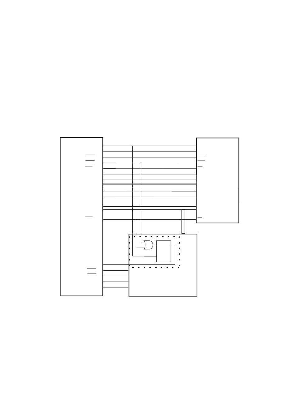
problem, prepare an external circuit as illustrated in Figure 4.10 - 6c to use an external wait cycle based on the
CAS signal, thereby extending I/O access to reserve data setup time.
Figure 10-6 Sample Circuit Solving a Fly - by Penalty Using External Wait Cycles Based on the CAS
Signal (CL = 2)
Note:
•
For CL = 3, provide two stages of MCLK - based FF to cause a delay of another cycle.
•
If any device requires an external wait cycle, add a logic gate to the RDY signal as required.
Figure 10-7 Timing Chart for Fly - by Penalty Solution Using External Wait Cycles Based on the CAS
This LSI
SDRAM
CLK
CKE
RAS
CAS
WE
DQMU
DQML
IA11-IA0
BA0
BA1
DQ15-DQ0
CS
I/O
FF
D
CK
Q
RDY
IORD
IOWR
DACK
DREQ
CS6
D31-D16
A15
A14
A11-A0
DQMUL
DQMUU
SME
SRAS
SCAS
MCLK
MCLKE