Operation – FUJITSU MB91460 SERIES FR60 User Manual
Page 897
881
Chapter 43 Stepper Motor Controller
3.Operation
3. Operation
The operation of the stepping motor controller is explained.
■
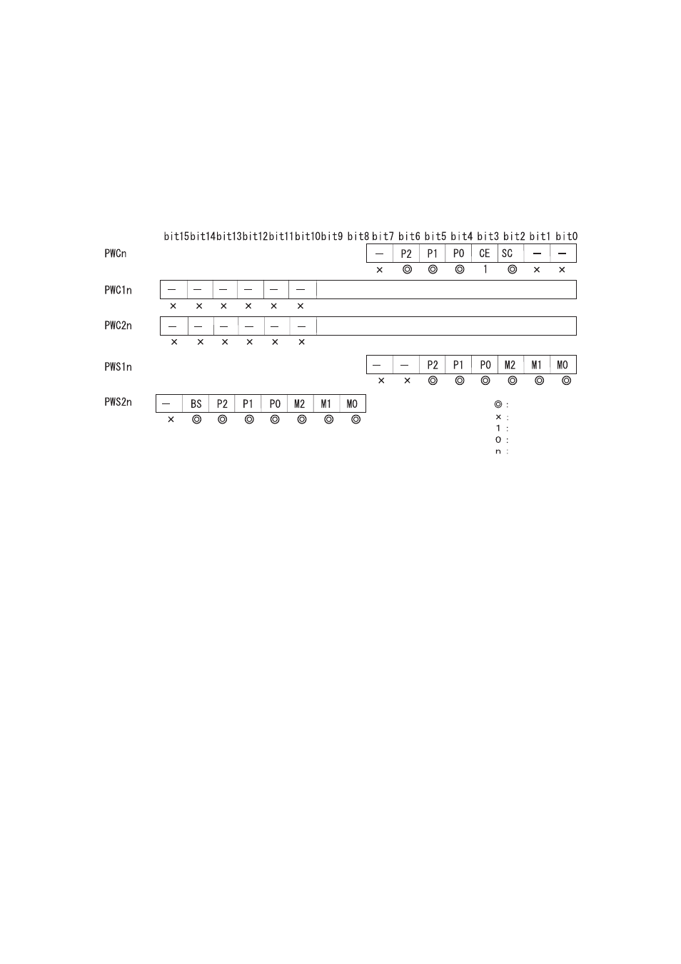
Setting Operation of Stepping Motor Controller
Figure 3-1 Setting of Stepping Motor Controller
■
Operation of PWM-pulse generator
When the counter is started (PWC: CE = 1), the counter starts incrementing from 00H on the selected count
clock rising. The PWM output pulse wave remains "H" until the value of the counter matches the value set to
PWM compare register, and then changes to and remains "L" until the value of the counter overflows (FF
H
-->
00
H
).
"Examples of PWM1&2 Waveform Output" shows the PWM waveform generated by the PWM
generator
PWM1 H width (compare value) is set.
PWM2 H width (compare value) is set.
Used bit
Not used bit
1 is set.
0 is set.
Channel No.
- XG Series P3NK-4452-01ENZD (614 pages)
- FPCAC14C (1 page)
- MCJ3230SS (161 pages)
- MBA3073NC (138 pages)
- T5140 (102 pages)
- T5140 (76 pages)
- MAM3367MC/MP (152 pages)
- MPC3045AH (185 pages)
- MB2142-02 (23 pages)
- MB15F86UL (6 pages)
- MHS2030AT (40 pages)
- MHW2100BS (296 pages)
- MHK2060AT (227 pages)
- Disk Drives MHK2060AT (227 pages)
- MCM3064SS (170 pages)
- Mainboard D1561 (45 pages)
- MHC2040AT (219 pages)
- D1961 (45 pages)
- DISK DRIVES MHM2100AT (231 pages)
- MHR2010AT (250 pages)
- MHZ2120BJ (320 pages)
- MCE3064AP (175 pages)
- LQFP-64P (16 pages)
- Solaris PCI GigabitEthernet 3.0 (115 pages)
- MAY2036RC (94 pages)
- MAB3091 (142 pages)
- MPE3XXXAT (191 pages)
- MHV2040AH (40 pages)
- MHW2040AC (278 pages)
- ETERNUSmgr P2X0-0202-01EN (64 pages)
- VSS Hardware Provider 2.1 (134 pages)
- MAG3182FC (61 pages)
- MAU3147NC/NP (130 pages)
- MAX3147RC (94 pages)
- MHV2160BT (296 pages)
- MHV2040AT (280 pages)
- MAW3300NC/NP (130 pages)
- DeskPower E623 (50 pages)
- MAG3182LC (133 pages)
- OPTICAL DISK DRIVES MDG3064UB (42 pages)
- MHF2021AT (225 pages)
- MHR2040AT (40 pages)
- Single Drive FTM7926FB (1 page)
- PG-FCS103 (98 pages)
- MAS3735FC (114 pages)