1 register details, Sound control register (sgcr) – FUJITSU MB91460 SERIES FR60 User Manual
Page 882
866
Chapter 42 Sound Generator
3.Registers
3.1 Register Details
■
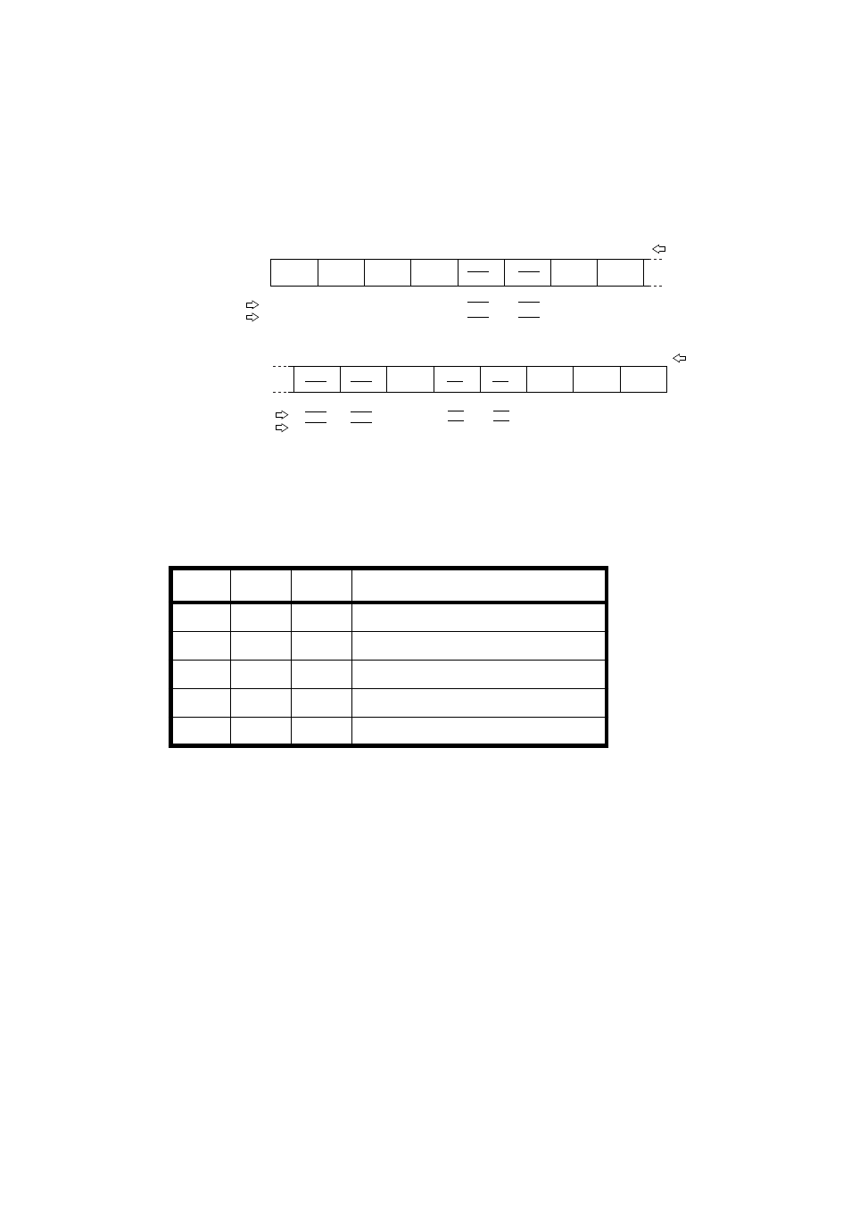
Sound Control Register (SGCR)
[bit 15] TST : Test bit
This bit is prepared for the device test. In any user application it should be set to "0".
[bits14 to12] S2 to S0 : Operation clock select bits
These bits specify the clock input signal for the Sound Generator.
[bit 9] BUSY : Busy bit
This bit indicates whether the Sound Generator is in operation. This bit is set to "1" upon the
ST bit is set to "1". It is reset to "0" when the ST bit is reset to "0" and the operation is
completed at the end of one tone cycle. Any write instruction performed on this bit has no
effect.
[bit 8] DEC : Auto-decrement enable bit
The DEC bit is prepared for an automatic decrement of the sound in conjunction with the
Decrement Grade register.
If this bit is set to "1", the stored value in the Amplitude Data register is decremented by
1(one), every time when the Decrement counter counts the number of tone pulses from the
toggle flip-flop specified by the Decrement Grade register.
[bit 5] TONE : Tone output bit
When this bit is set to "1", the SGO signal becomes a simple square-waveform (tone pulses)
from the toggle flip-flop. Otherwise it is the mixed (AND logic) signal of the tone and PWM
pulses.
S2
S1
S0
Clock input
0
0
0
CLK
0
0
1
1/2 CLK
0
1
0
1/4 CLK
0
1
1
1/8 CLK
1
0
0
1/16 CLK
7
6
5
4
3
2
1
0
TST
DEC
SGCRL
(R/W)
(R/W)
(R/W)
(R/W)
(R/W)
(R/W)
(0)
(0)
(0)
(0)
(0)
(0)
Bit number
Sound Control register
Address: 000199
H
Read/write
Initial value
15
14
13
12
11
10
9
8
S1
S0
TONE
INTE
INT
ST
SGCRH
Bit number
Read/write
Initial value
Address: 000198
H
(R/W)
(0)
(R)
(0)
(0)
(R/W)
BUSY
S2
(R/W)
(0)